
Clamp connection and release device

Inactive Publication Date: 2005-01-27
JANOVICI DENNIS S +3
View PDF27 Cites 4 Cited by
  • Summary
  • Abstract
  • Description
  • Claims
  • Application Information

AI Technical Summary

Benefits of technology

[0013] The clamp connector and release device for facilitates connection and easy release between a pair of registering connectors, such as a plug and a socket, thereby providing an inline connection which can be established and released as needed.
[0014] The clamp of the invention has particular application when used between a truck and trailer, whereby the various systems and devices on a trailer, such as lighting, air conditioning, braking and other systems, may be connected to the truck so that they can be operated from the truck. The clamp of the invention may establish inline connections of electrical, hydraulic or pneumatic type, and is designed so as to facilitate the connection, and, most importantly, allow ease or efficiency with respect to the release, since the plug and socket connection may often be tight fitting and require a significant amount of force to separate.
[0015] While the invention has as an important application in the connection of systems between a truck and trailer, the invention is not to be construed as being limited in this regard. The clamp of the invention may be useful and applicable in any situation where a plug may be connected to a socket, since the clamp of the invention significantly facilitates ease of separation so that the plug can be released or withdrawn from the socket.

Problems solved by technology

For this reason, the plug connection from the trailer to the socket or outlet of the truck is usually a very firm one, often requiring a significant amount of force to disconnect the two.
Moreover, the connections may be located at positions which are difficult to access, making maneuverability by the operator difficult for the purposes of separating the plug from the socket.

Method used


Image

  • Clamp connection and release device
  • Clamp connection and release device
  • Clamp connection and release device

Examples


Embodiment Construction

[0032] Reference is now made to the drawings accompanying this application, which show various views of the clamp connector and release device of the invention, in different views, as well as the elements and components which make up the clamp.

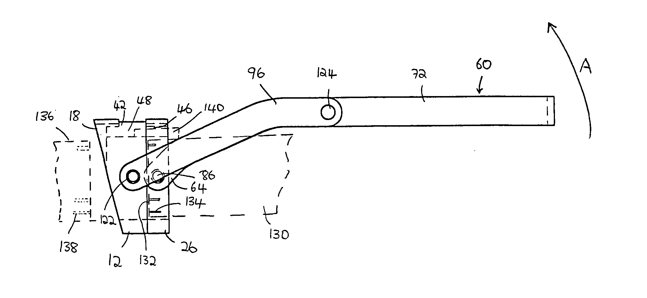
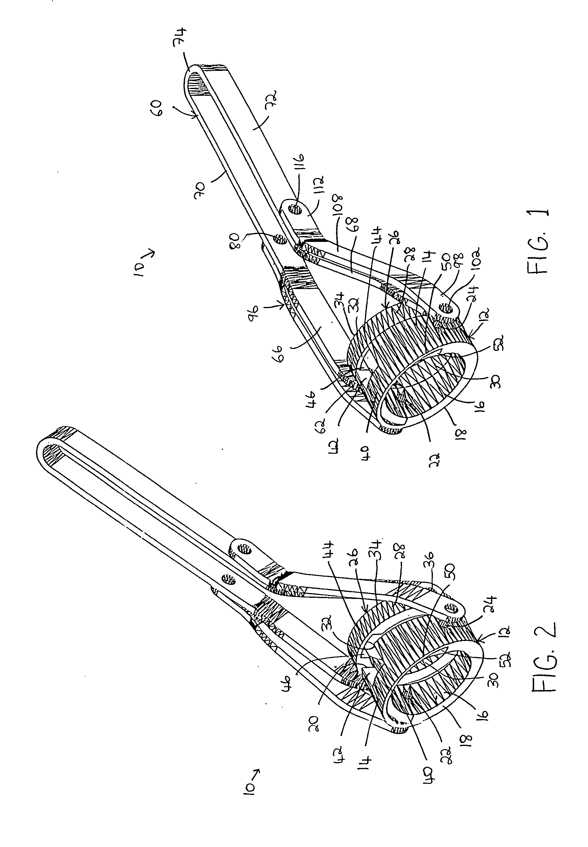
[0033] With particular reference to FIGS. 1 and 2 of the drawings, a perspective view of a clamp 10 of the invention is shown in each of these Figures, with FIG. 1 showing the clamp 10 in a closed position, when a plug and socket are connected, and with FIG. 2 showing the clamp 10 in an open position, when a plug and socket are disconnected, the clamp 10 having been maneuvered so as to disconnect the plug from the socket.

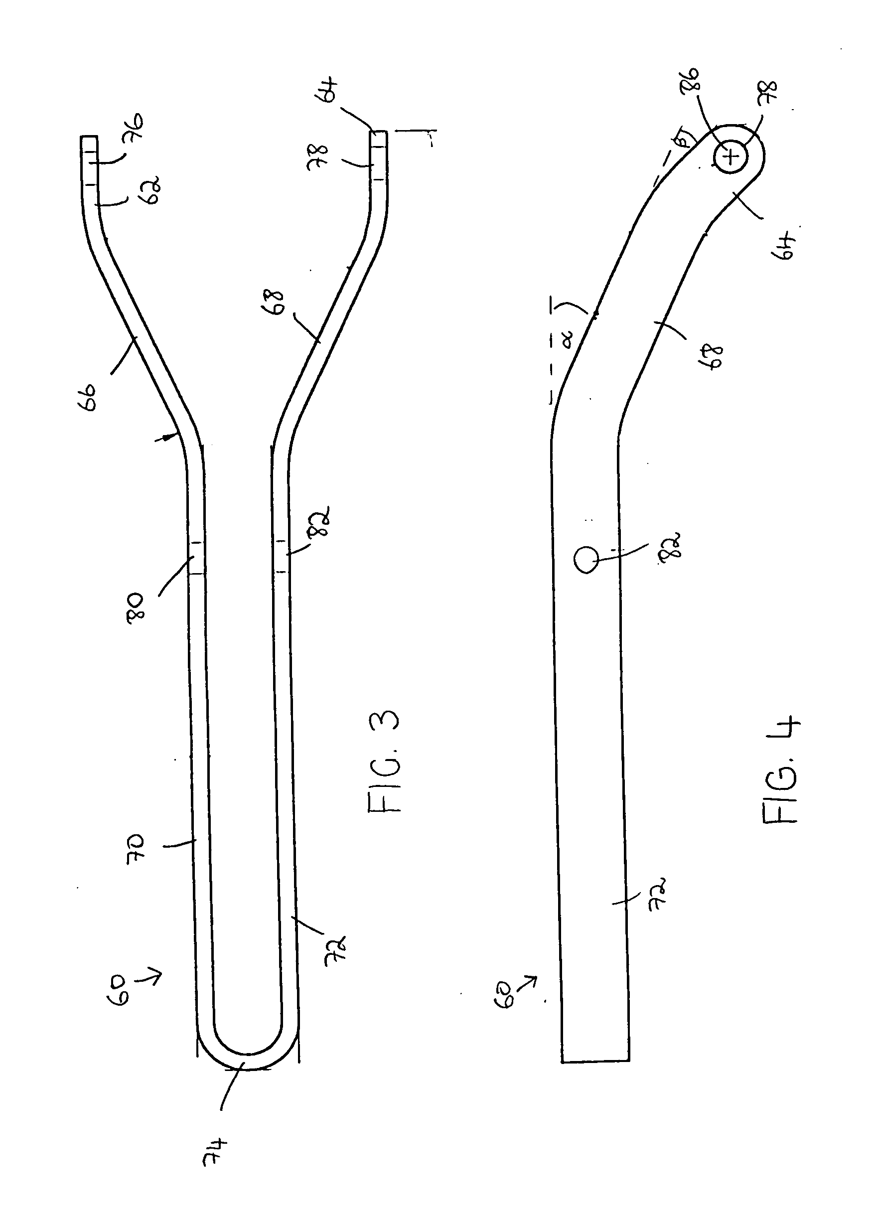
[0034] The clamp 10 comprises a sleeve 12, a ring 26, a handle 60 and a bracket 96, all arranged and connected with respect to each other as will be described.

[0035] The clamp 10 comprises the sleeve 12 which is of substantially cylindrical shape, the sleeve 12 having an outer surface 14, an inner surface 16, a leading end ...


PUM

PropertyMeasurementUnit
Shapeaaaaaaaaaa
Distanceaaaaaaaaaa

Abstract

A release bracket for an inline releasable plug and socket type connection comprises a collar having a forward end, a rear end and defining an opening having an axis. An inline plug or socket component is slidably accommodated in the opening of the collar, the plug or socket component having a forward end and a rear end. A handle having a first end is pivotally connected to the collar for rotation about the pivotal connection, and a bracket is pivotally connected at one of its ends to the plug or socket component and pivotally connected at an opposing end thereof to the handle. When the handle is rotated about its pivotal connection to the collar, the collar and the plug or socket component move relative to each other between a first position where the forward end of the plug or socket component is a distance from the forward end of the collar and a second position where the plug or socket component is a greater distance from the forward end of the collar.

Description

CROSS REFERENCE TO RELATED APPLICATIONS [0001] This application is a continuation-in-part application of U.S. patent application Ser. No. 09 / 894,930 filed Jun. 28, 2001, which is incorporated herein by reference in its entirety.FIELD AND BACKGROUND OF THE INVENTION [0002] This invention relates to a clamp connection and release device. More particularly, the invention is for a clamp connection and release device for inline connections for cables, plugs and sockets, electrical connections, as well as hydraulic and pneumatic connections. These connections are generally referred to as couplings. [0003] There are many instances where it is necessary to connect couplings, for subsequent easy release, in order to form an electric or other connection between, for example, a switch or power source and a device which it activates. In one application, when a trailer is connected to a truck or tractor, it is not only necessary to ensure the physical connection between the truck and trailer, bu...

Claims


Application Information

Patent Timeline
IPC IPC(8): B25B27/10F16L1/09H01R13/629H01R13/633H01R13/639
CPCB25B27/10F16L1/09H01R13/62933H01R13/6335H01R13/6395Y10T29/53678Y10T29/53717Y10T29/53896Y10T29/53917Y10T403/7062Y10T29/49822Y10T29/53683Y10T29/49895
Inventor JANOVICI, DENNIS S.ZAHN, ANTHONY JR.WHITE, ROBERTSWEENEY, MATT
Owner JANOVICI DENNIS S
Learn More