Electromotive bed
a technology of electromotive beds and electromotive beds, applied in the direction of rigid tables, nursing beds, medical science, etc., can solve the problems of inability to provide users with natural and comfortable sense, inconvenient use, complex structure of products, etc., to improve nursing conditions, reduce the effect of affecting the nursing condition and reducing the number of patients
- Summary
- Abstract
- Description
- Claims
- Application Information
AI Technical Summary
Benefits of technology
Problems solved by technology
Method used
Image
Examples
example 1
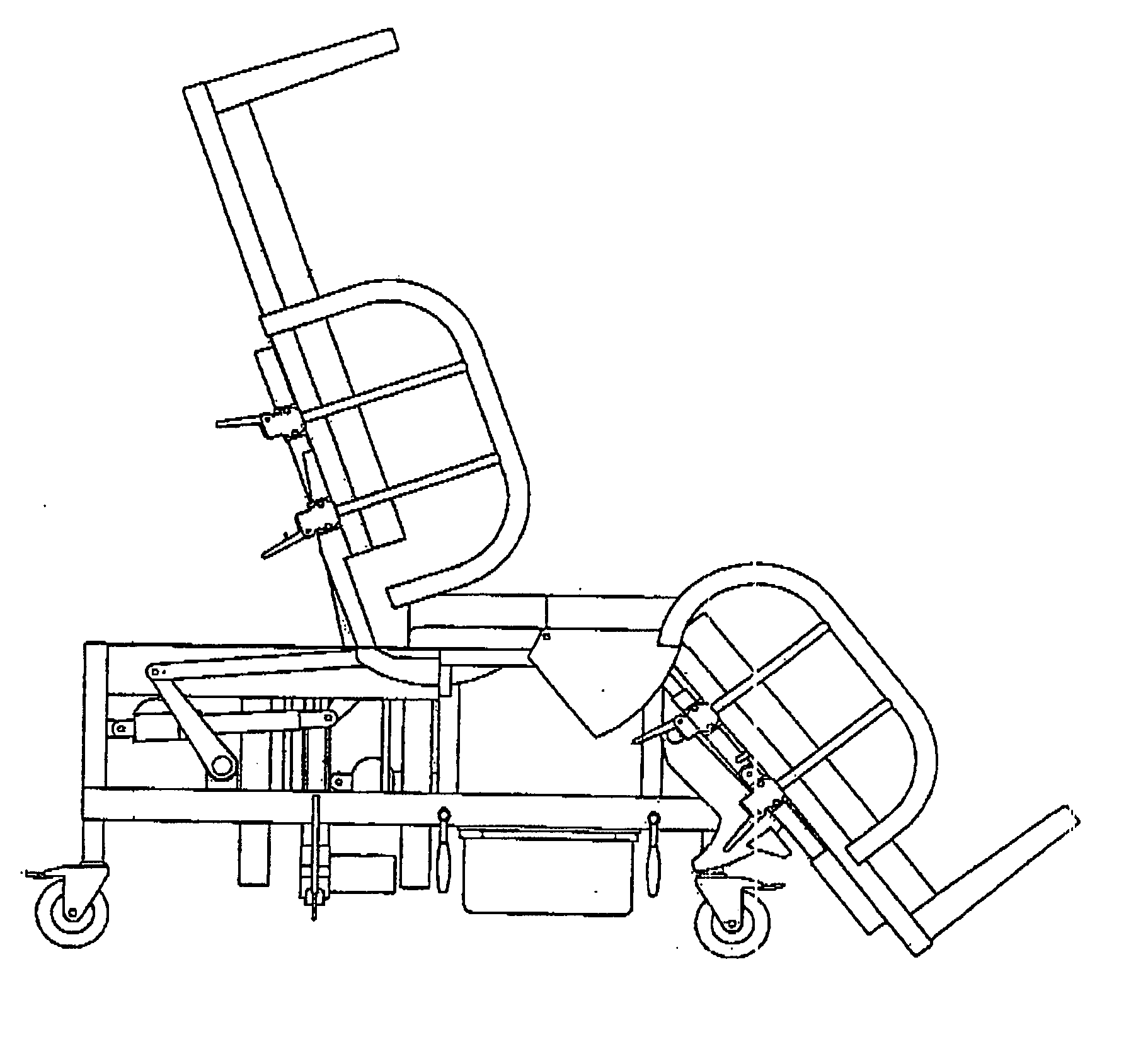
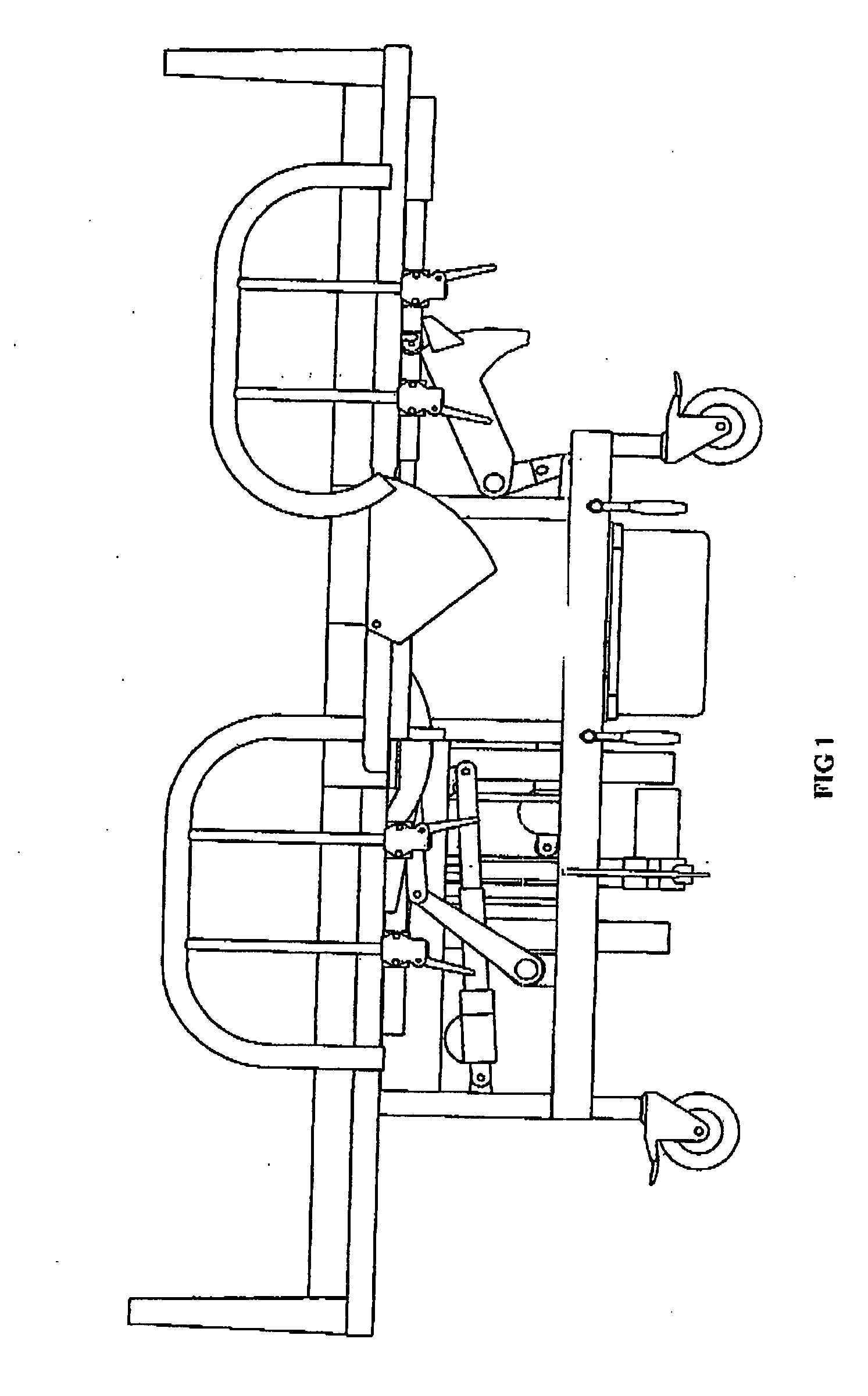
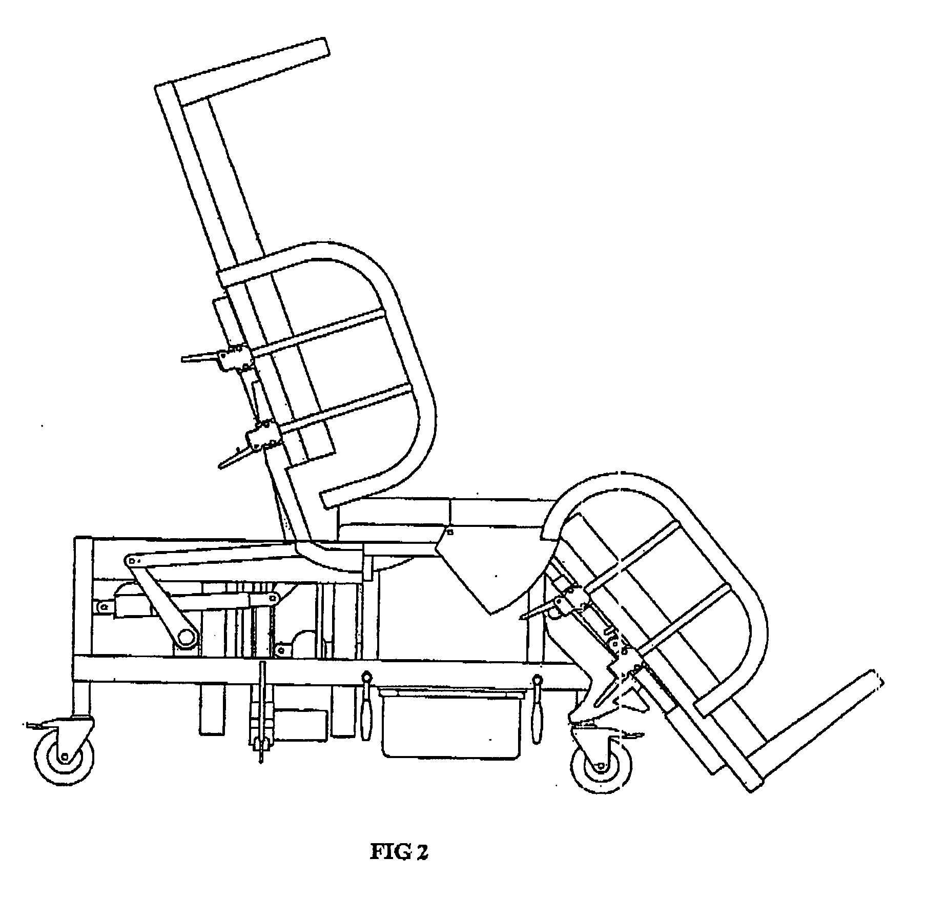
[0038] As shown in FIGS. 1 and 2, the electromotive bed of the example includes a back raising device and a leg lowering down device, thus it enable the patient relieve himself comfortably on the electromotive bed in sitting position.
[0039] As shown in FIG. 3, two rectangular through holes 2 are opened in the middle upper portion of the mattress 1 along its width line, and a bole 3 for defection is opened at an appropriate position in the middle lower portion; a turnover supporting block 4 is installed in each through hole 2, and the lateral of the turnover supporting block 4 is perpendicular to the axial line of the electromotive bed.
[0040] As shown in FIG. 4, five shaft pin holes 5 are formed symmetrically on both left and right sides of the upper end of peach-shape turnover supporting block 4, and shaft pins 6 are installed in the second shaft pit holes 5 from outside respectively, a slit 7 is opened at the nose bit of the turnover supporting block along the center line.
[0041]...
example 2
[0051] This example further provides a preferable scheme for the turnover part of the electromotive bed invention.
[0052] As shown in FIG. 7, two crossbar shaft pin supporting plates 14 are installed correspondingly on the longer sidewalls of the through hole 2, and the gullet is formed at the upside of the supporting palate 14; both ends of two shaft pin 6 set symmetrically protrude from the surface of the turnover supporting block 4 and are locked respectively in the gullets 15 on one end of the two shaft pin supporting plates 14; in such a way, the turnover supporting block 4 is clamped by two crossbar shaft pin supporting plates 14 and is installed stably and rotatablely on the electromotive bed through the shaft pin 6. The width of the turnover supporting block 4 in this example is 6 cm.
[0053] The load transfer device in this example includes a rotating shaft 22 fixed on the electromotive bed, and a deflector arm 17 and a first gear 23 are mounted around the rotating shaft 22;...
example 3
[0057] This example further provides a preferable scheme for the defecation device of the electromotive bed according to the invention.
[0058] As shown in FIG. 8, the porefilling pads 18 make rotatable connects rotatablely with a cross rod 32 through four sleeves 31 (each two as a group). The cross rod 32 integrated with the crank 33, minor axis 34, second gear 35 into one block and can rotate around the bearing block 37.
[0059] As shown in FIG. 9, the second rack rod 36 engages with the second gear 35, and further connects to and second unit head 28 through the bearing rod 30. The second unit head 28 drives the second rack rod 36 to move back and forth in a straight line, and make the second gear 35 to rotate back and forth and drive the crank 33 through the minor axis 34 fixed to the second gear 35, and further drive the cross rod 32 to waggle. In this way, the sleeves 31 formed parallelly at both sides of the bottom surface of porefilling pad 18 waggle together with the cross rod...
PUM
 Abstract
Description
Claims
Application Information
 - R&D Engineer
- R&D Manager
- IP Professional
- Industry Leading Data Capabilities
- Powerful AI technology
- Patent DNA Extraction
Browse by: Latest US Patents, China's latest patents, Technical Efficacy Thesaurus, Application Domain, Technology Topic, Popular Technical Reports.
© 2024 PatSnap. All rights reserved.Legal|Privacy policy|Modern Slavery Act Transparency Statement|Sitemap|About US| Contact US: help@patsnap.com


