Eureka AIR delivers breakthrough ideas for toughest innovation challenges, trusted by R&D personnel around the world.

Encapsulation device and methods of use

Inactive Publication Date: 2005-01-20
DEBEER NICHOLAS
View PDF26 Cites 122 Cited by
  • Summary
  • Abstract
  • Description
  • Claims
  • Application Information

AI Technical Summary

Benefits of technology

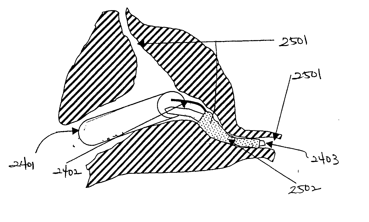
[0005] In one embodiment of the present invention, there is provided an encapsulation device which includes an expandable, porous body having a cavity therein, the body having a sealed end and a sealable end, where the body is configured to receive one or more fluids through a port in the sealable end, where the body is configured to expand to conform to a shape of a target, and where the sealable end may be sealed to prevent leakage into the body.
[0010] The port in the sealable end may comprise a valve configured to open to receive one or more fluids and close to prevent leakage into the body.
[0013] An encapsulation device in accordance with another embodiment of the present invention includes an expandable, porous body having a cavity therein, the body having a sealed end and a sealable end, where the body is configured to receive one or more fluids through a port in the sealable end, where the body is configured to expand to conform to a shape of a target, where the sealable end may be sealed to prevent leakage into the body, where the body comprises porous membrane such as expanded Polytetrafluoroethylene (ePTFE), and further, where the port in the sealable end receives a first fluid into said cavity to expand the body to conform to the shape of the target, and wherein the port receives a second fluid into said cavity which displaces the first fluid by diffusing the first fluid through the pores in the body and which cures to secure the body to the target.
[0017] The port in the sealable end may comprise a valve configured to open to receive one or more fluids and close to prevent leakage into the body.
[0020] A method of providing an encapsulation device to a desired location in accordance with still another embodiment of the present invention includes expanding a porous body to conform to a shape of a target by introducing a first fluid into an opening in the body, introducing a second fluid into the porous body to displace the first fluid through the porous body, and allowing the second fluid to cure to secure the porous body to the target. In one embodiment, either the first fluid or the second fluid may be radiopaque to allow visibility under X-ray or fluoroscopy to assist, guide or monitor the deployment of the encapsulation device.

Problems solved by technology

It is difficult to deploy complex shapes through small portals in the body of an animal.
For many body conditions, it is often the case that invasive surgical procedures are necessitated due to the fact that isolation and application of a target treatment is often difficult given the complexity of the portals in the animal body.
However, existing approaches have limitations due to the shortcomings of the stents, whether medically coated or not.
Moreover, because of the complexity of the shapes in the various areas of the animal body, one challenge is to provide a three dimensional structure which may be easily deployed to the target area of the body, and provide structural integrity at the desired site, whether for physical support or for controlled release of a particular medication.
Additionally, there are many biocompatible and bioactive adhesives and non-adhesive materials that can change shape from liquid to solid or semi-solid in the body.
But there are few ways of providing safe containment of such materials in the body.

Method used


Image

  • Encapsulation device and methods of use
  • Encapsulation device and methods of use
  • Encapsulation device and methods of use

Examples


Embodiment Construction

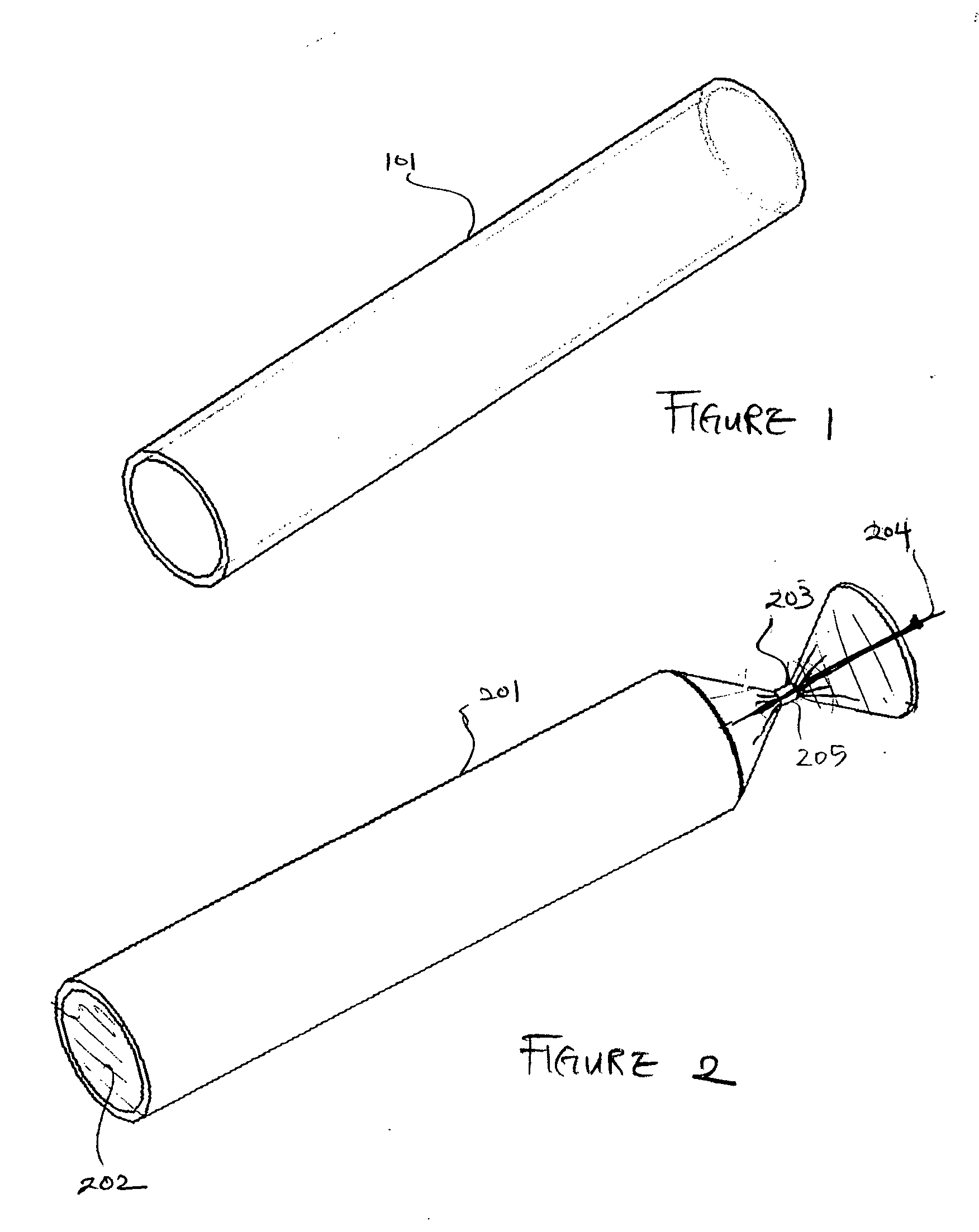
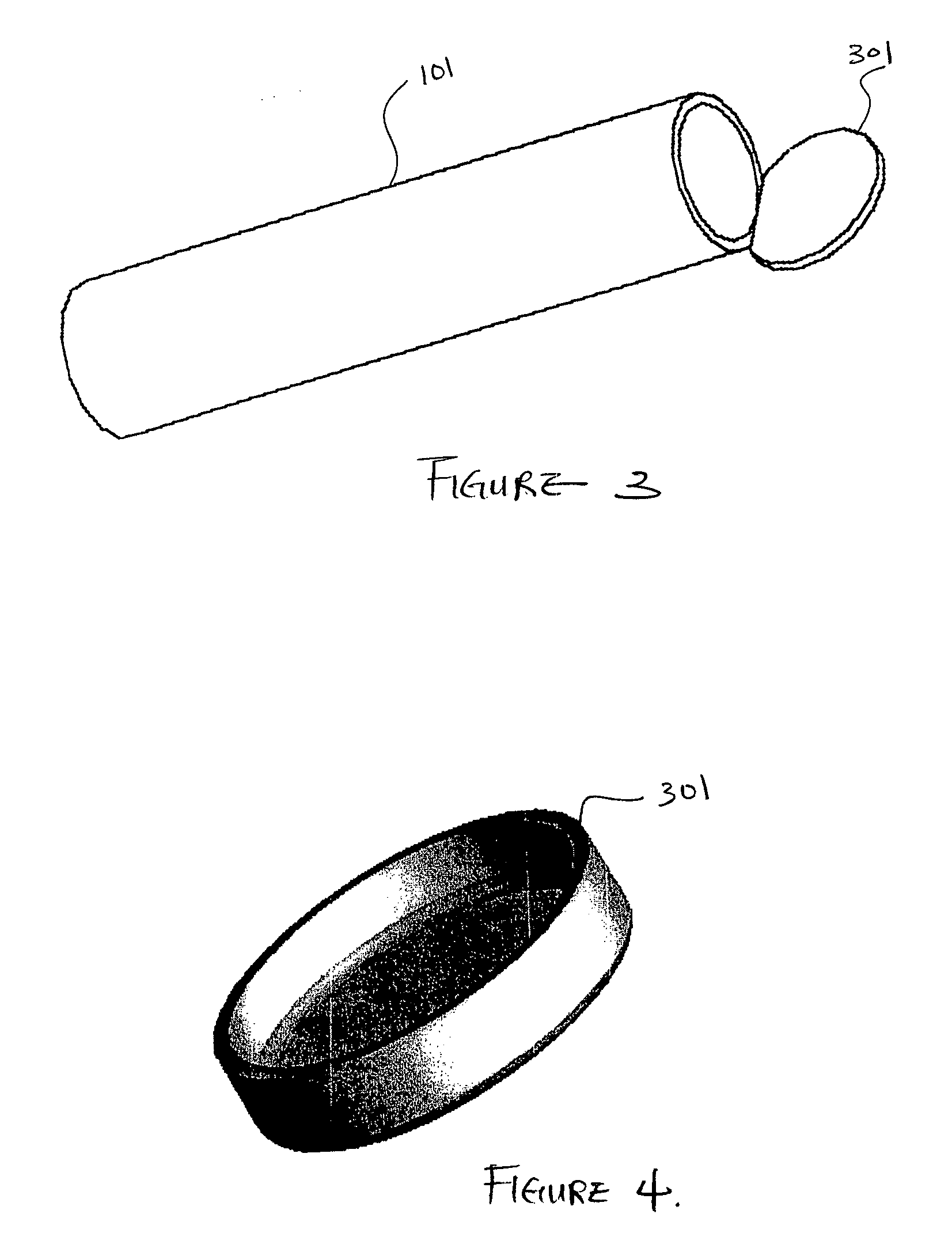
[0090]FIG. 1 is a three-dimensional perspective view of a membrane for use as an encapsulation device in one embodiment. Referring to FIG. 1, encapsulation membrane 101 is shown in tubular form. In one embodiment, the encapsulation device may be comprised of membrane 101 which includes expanded Polytetrafluoroethylene (ePTFE) that is made by expanding PTFE tubing under controlled conditions during the manufacturing process. The amount of expansion in ePTFE during manufacturing process is typically referred to as an internodal distance that typically ranges between 1 micron to 200 microns. The manufacturing process alters the physical properties of the PTFE tubing by creating microscopic pores in the structure of the PTFE tubing.

[0091] In this manner, the ePTFE differs from the conventional PTFE tubing in that the ePTFE material is microporous, soft, flexible, has a lower dielectric constant, increased linear strength, and improved biocompatibility. The structure of ePTFE is unique ...


PUM

PropertyMeasurementUnit
Viscosityaaaaaaaaaa
Shapeaaaaaaaaaa
Adhesivityaaaaaaaaaa

Abstract

An encapsulation device having an expandable, porous body with a cavity, the body having a sealed end and a sealable end, where the body is configured to receive one or more fluids through a port in the sealable end, the body is configured to expand to conform to a shape of a target, and where the sealable end may be sealed to prevent leakage into the body, and a method if using the encapsulation device, is disclosed. The body may comprise porous membrane including expanded Polytetrafluoroethylene (ePTFE), polyester fiberfill, metal / polymer mesh, and perforated or porous polymer / metal. The target may include a location within the human body. The port in the sealable end is configured to receive a first fluid into the cavity to expand the body to conform to the shape of the target, and the port is further configured to receive a second fluid into the cavity which displaces the first fluid by diffusing the first fluid through the pores in the body and which cures (such as, by an ultraviolet light source) to secure the body to the target. Optionally, the introduction of the second fluid may be unnecessary when the first fluid includes the desired filler material for the encapsulation device.

Description

BACKGROUND OF THE INVENTION [0001] The present invention relates to an application for three-dimensional space filling encapsulation devices which may be filled with a bioactive agent or anchored in vivo. More specifically, the present invention relates to applications for encapsulation through filling a member directly or through diffusion, displacement of one or more fluids, and the replacement of the fluids with one or more other fluids or hydrogels. Wire assisted membrane shape formation may aid delivery or final dimension of the encapsulation. [0002] It is difficult to deploy complex shapes through small portals in the body of an animal. For many body conditions, it is often the case that invasive surgical procedures are necessitated due to the fact that isolation and application of a target treatment is often difficult given the complexity of the portals in the animal body. Use of stents and the like are commonplace for deploying medication and so on. However, existing approac...

Claims


Application Information

Patent Timeline
IPC IPC(8): A61B17/00A61B17/68A61B17/70A61B17/88A61F2/00A61F2/30A61F2/44
CPCA61B17/68A61F2220/0075A61B2017/00557A61F2/07A61F2/44A61F2/441A61F2/442A61F2/856A61F2/88A61F2/92A61F2/945A61F6/20A61F2002/067A61F2002/077A61F2002/30011A61F2002/30016A61F2002/3008A61F2002/30092A61F2002/30224A61F2002/30242A61F2002/30581A61F2002/30583A61F2002/30586A61F2002/30677A61F2002/30971A61F2002/4435A61F2002/444A61F2002/4495A61F2210/0014A61F2210/0085A61F2230/0069A61F2230/0071A61F2250/0019A61F2250/0023A61F2250/0098A61F2/89A61F2002/072A61F2220/005A61F2220/0058A61B17/7098
Inventor DEBEER, NICHOLAS
Owner DEBEER NICHOLAS
Why Eureka
Eureka Blog
Learn More