
Randomly controlled roulette game operation

Inactive Publication Date: 2005-01-20
RHOTEN LARRY J
View PDF0 Cites 54 Cited by
  • Summary
  • Abstract
  • Description
  • Claims
  • Application Information

AI Technical Summary

Benefits of technology

[0017] Still another aspect of my invention is conducting a game via the internet. The techniques are the same as for a video or virtual game. In addition, appropriate encryption techniques are used to keep communications confidential and prevent cheating. DRAWING SUMMARY

Problems solved by technology

A person who actuates the isolated manually actuable activation means, therefore, is unable to predict or control either the exact time the ball will be launched or its ultimate stopping place.

Method used


Image

  • Randomly controlled roulette game operation
  • Randomly controlled roulette game operation
  • Randomly controlled roulette game operation

Examples


Embodiment Construction

(FIG. 1-4)

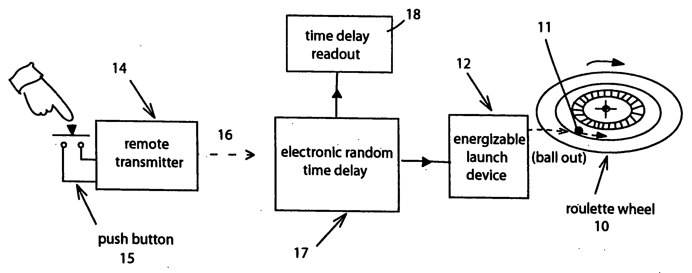
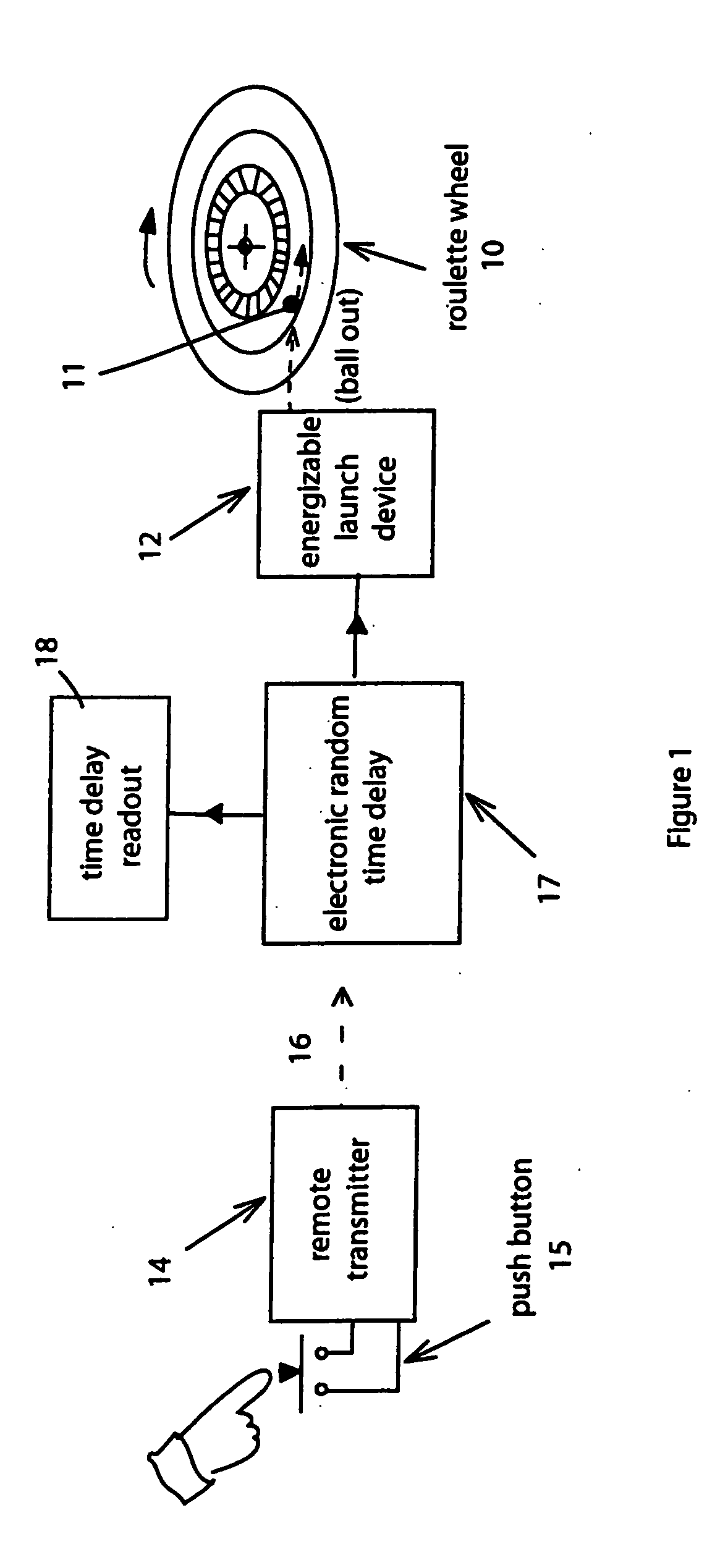
[0028] Referring now to the drawings, FIG. 1 shows a roulette wheel 10 onto which a ball 11 is to be launched. An energizable launch device or mechanism 12 is available to provide the actual launching of the ball. A remote transmitter 14 is controlled by a push button 15. When the button 15 is pushed the transmitter generates a Start Game signal 16 that is then transmitted to an electronic random time delay circuit 17. The transmission of the Start Signal 16 is represented in FIG. 1 by a dotted line and arrow, indicative of the fact that any of several different means may be utilized for communicating a Start Game signal to the electronic random time delay circuit 17. Also associated with the time delay circuit 17 is a time delay readout 18 which visibly indicate the actual amount of time that transpires after the start button 15 is pressed and before a Launch Signal is generated to energize the launch mechanism 12.

[0029] In accordance with the invention a random time per...


PUM


Abstract

A method of controlling at least one of the launch time of the ball, the speed of rotation of the wheel, and the speed of movement of the ball, in such a way that none of those factors is under the immediate control of a game manager; and displaying information to confirm the randomness of the operation.

Description

PRIORITY CLAIM [0001][0001] I claim priority of my copending U.S. patent application Ser. No. 10 / 693,741 filed Oct. 24, 2003; and of my three U.S. Provisional Applications Ser. No. 60\484990 filed Jul. 3, 2003; Ser. No. 60\495641 filed Aug. 15, 2003; and Ser. No. 60\502456 filed Sep. 11, 2003.FIELD OF THE INVENTION [0002] This invention relates to improvements in gaming devices, and particularly to roulette table games, or video simulations thereof, or in coin operated gaming devices or in internet gaming. BACKGROUND OF THE INVENTION [0003] In the game of roulette, which is played at many gaming houses in the United States and elsewhere, a dealer employed by the gaming house releases a ball which then travels around the periphery of a rotating wheel having circumferentially arranged stopping places, until the ball finally stops at a particular stop. The stopping place of the ball, and a number associated with that stopping place, determines whether particular players have won or los...

Claims


Application Information

Patent Timeline
IPC IPC(8): A63F5/00
CPCA63F5/00A63F5/0035A63F2250/1089A63F7/2472A63F5/0076
Inventor RHOTEN, LARRY J.
Owner RHOTEN LARRY J
Learn More