Non-volatile storage device control method
a non-volatile storage device and control method technology, applied in the direction of memory address formation, micro-instruction address formation, memory address/allocation/relocation, etc., can solve the problem of inability to complete data writing in the correct physical block, and difficulty in judging whether one physical block is truly erased or no
- Summary
- Abstract
- Description
- Claims
- Application Information
AI Technical Summary
Benefits of technology
Problems solved by technology
Method used
Image
Examples
first embodiment
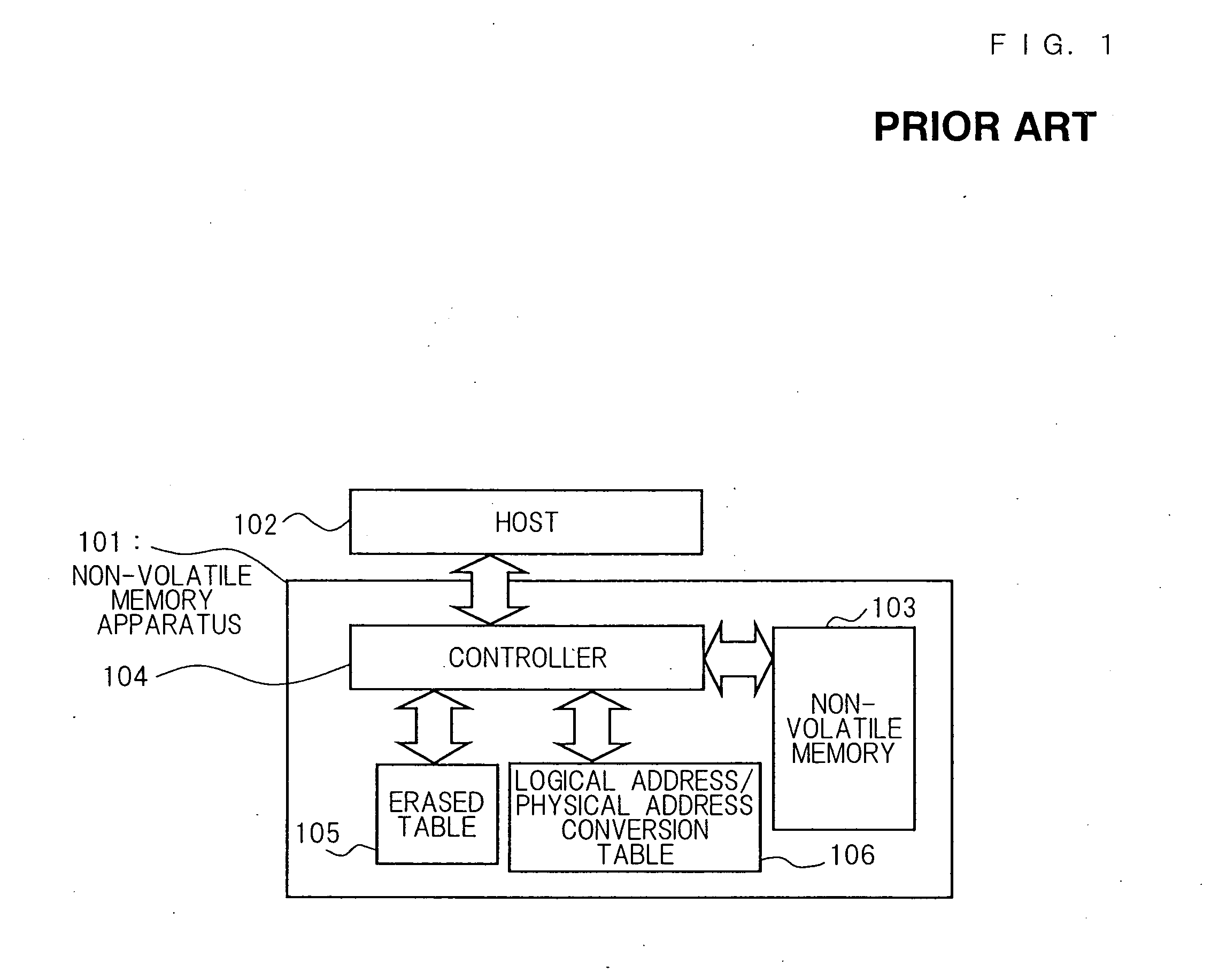
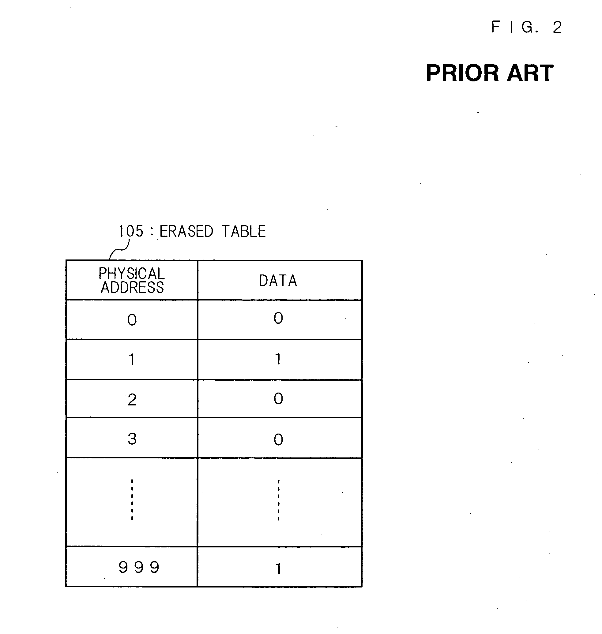
[0091] Non-volatile memory apparatus in accordance with the first embodiment will be described with reference to FIG. 1 through FIG. 7. In FIG. 1, a reference numeral 101 denotes a non-volatile memory apparatus, a reference numeral 102 denotes a host. A non-volatile memory apparatus 101 has a non-volatile memory 103, a controller 104, an erased table 105, and a logical address / physical address conversion table 106. In the first embodiment, the non-volatile memory apparatus 101 is a memory card, the host 102 is a cellular phone, and the non-volatile memory 103 is a flash memory. Since FIG. 1 through FIG. 4 are identical to the conventional art, its detailed description will be omitted.
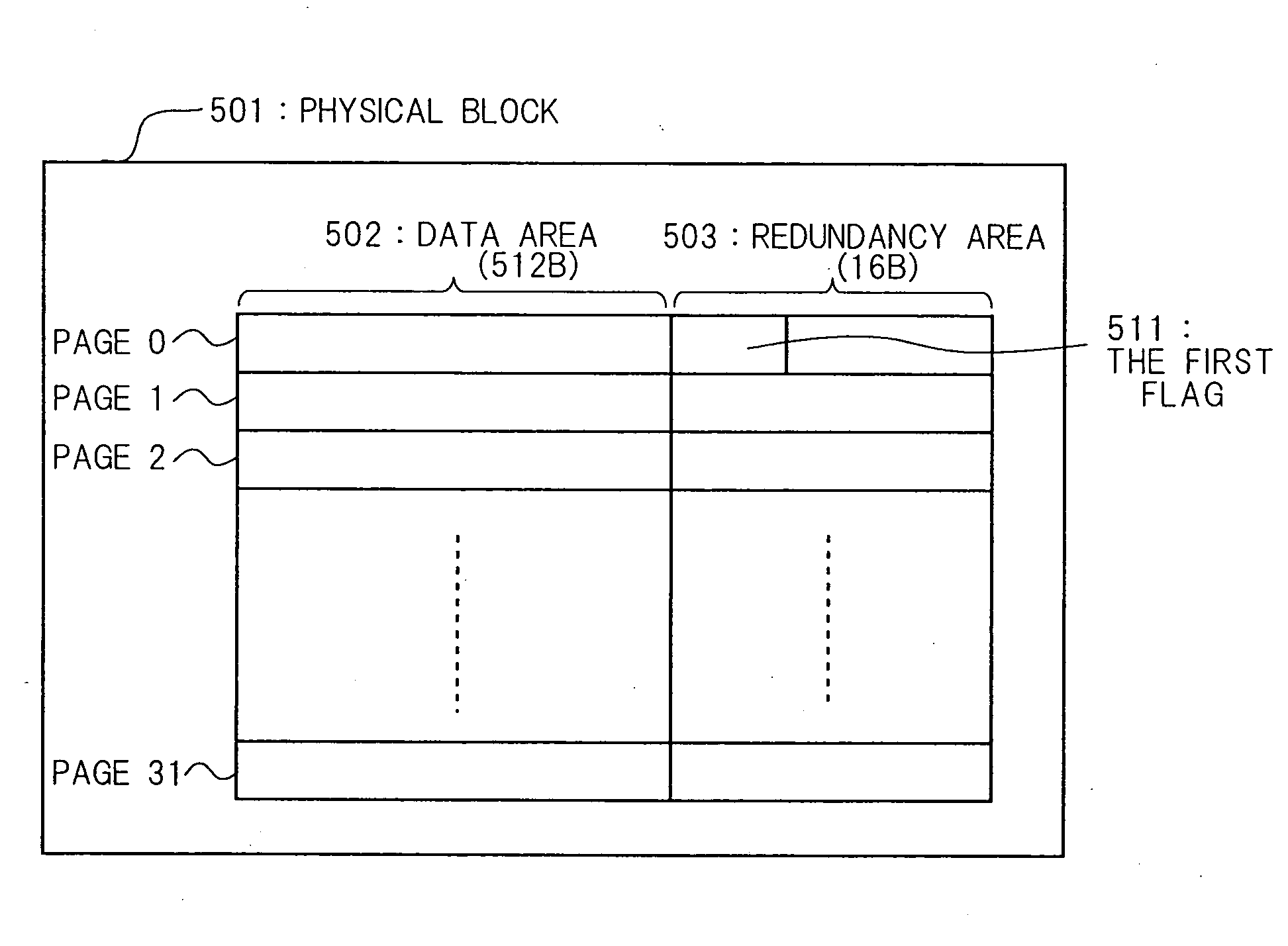
[0092]FIG. 5 shows the configuration of a physical block of a non-volatile memory 103 in accordance with the present invention. A physical block 501 consists of 32 pages. The capacity of a single page is 528 bytes, and is divided into a data area 502 of 512 bytes and a redundancy area 503 of 16 bytes. ...
second embodiment
[0104] The control method of a non-volatile memory apparatus in accordance with the second embodiment will be described with reference to FIG. 1 through FIG. 3 and FIG. 8 through FIG. 11. Since FIG. 1 through FIG. 3 are identical with the conventional art and the first embodiment, its description will be omitted. FIG. 8 shows the configuration of a physical block of a non-volatile memory 103 in accordance with the second embodiment of the present invention. In FIG. 8, an identical numeral is affixed to parts identical with the conventional art (FIG. 24).
[0105] Difference of the physical block in accordance with the second embodiment from the configuration of a physical block in the conventional art is that it has a second flag 801 in the redundancy area 503 of a pre-determined page (page 31 which is the last page, in the second embodiment). The second flag 801 is represented in a plurality of bit data in order to enhance data reliability. In the second embodiment, the second flag i...
third embodiment
[0124] The control method of a non-volatile memory apparatus in accordance with the third embodiment will be described with reference to FIG. 11 and FIG. 12. The physical block 501 of the non-volatile memory 103 in accordance with the third embodiment has both the first flag and the second flag. The first flag 511 and the second flag 801 which the physical block in accordance with the third embodiment has are identical to the first flag 511 in accordance with the first embodiment and the second flag 801 in accordance with the second embodiment, respectively.
[0125] Data rewriting method of a non-volatile memory apparatus 101 in accordance with the third embodiment will be described with reference to FIG. 12. FIG. 12 is a flowchart of a data rewriting method of a non-volatile memory apparatus 101 in accordance with the third embodiment. In FIG. 12, an identical numeral is affixed to steps identical with FIG. 6 of the first embodiment and FIG. 9 of the second embodiment.
[0126] When a...
PUM
 Abstract
Description
Claims
Application Information
 - R&D
- Intellectual Property
- Life Sciences
- Materials
- Tech Scout
- Unparalleled Data Quality
- Higher Quality Content
- 60% Fewer Hallucinations
Browse by: Latest US Patents, China's latest patents, Technical Efficacy Thesaurus, Application Domain, Technology Topic, Popular Technical Reports.
© 2025 PatSnap. All rights reserved.Legal|Privacy policy|Modern Slavery Act Transparency Statement|Sitemap|About US| Contact US: help@patsnap.com


