
Perpendicular magnetic recording element, magnetic head, magnetic head device and magnetic recording/reproducing apparatus

a technology of magnetic recording element and magnetic head, which is applied in the direction of data recording, head winding construction, instruments, etc., can solve the problems of destabilizing the structure of the magnetic domain, and affecting the quality of the recording

Active Publication Date: 2005-01-20
TDK CORPARATION
View PDF1 Cites 37 Cited by
  • Summary
  • Abstract
  • Description
  • Claims
  • Application Information

AI Technical Summary

Benefits of technology

It is an object of the present invention to provide a perpendicular magnetic recording element that eliminates the problem of pole erase inherent in perpendicular magnetic recording, and a magnetic head, a magnetic head device and a magnetic recording / reproducing apparatus achieved by using this perpendicular magnetic recording element.
In addition, the writer magnetic pole film of the perpendicular magnetic recording element according to the present invention includes a magnetic bias film which applies a magnetic bias along the easy axis to the soft magnetic film. As a result, when a write operation is not executing the soft magnetic film included in the writer magnetic pole film receives the magnetic bias applied by the magnetic bias film and is magnetized in a stable manner along the easy axis perpendicular to the direction of the perpendicular writer magnetic field. Thus, the problem of the pole erase phenomena attributable to the residual magnetic flux generated while the write operation is not executed can be eliminated with a high level of reliability according to the present invention.

Problems solved by technology

However, while the use of the type of material described above to constitute the magnetic pole improves the recording capability, it leads to a problem of so-called pole erase at a perpendicular magnetic writer head whereby a signal having been recorded by a writer magnetic pole becomes erased when a write operation is not executed.
However, since the front end of the writer magnetic pole width comes to narrow, shape form anisotropy is induced which destabilizes the structure of the magnetic domain.
This instability in the magnetic domain structure is thought to be the root cause of the pole erase phenomena, since it induces trapping at the magnetic wall, which keeps the direction of the magnetization unchanged toward the medium even after the write operation ends, allowing the magnetic flux to leak into the medium, and it makes erasing the recorded data on the medium.
In addition, while there is a longitudinal writer head in the related art adopting a structure having a hard, thin magnetic film arranged over the shield area, the distance to the soft magnetic film is considerable and thus, this structure is not effective enough to prevent pole erase at the perpendicular writer head.
Furthermore, if the magnetic pole width is further reduced to keep pace with the ever increasing need to improve recording density, the shape form anisotropy will become even more dominant to allow a significant extent of residual magnetization at the magnetic pole tip toward the medium surface, which is bound to exacerbate the problem.

Method used


Image

  • Perpendicular magnetic recording element, magnetic head, magnetic head device and magnetic recording/reproducing apparatus
  • Perpendicular magnetic recording element, magnetic head, magnetic head device and magnetic recording/reproducing apparatus
  • Perpendicular magnetic recording element, magnetic head, magnetic head device and magnetic recording/reproducing apparatus

Examples


Embodiment Construction

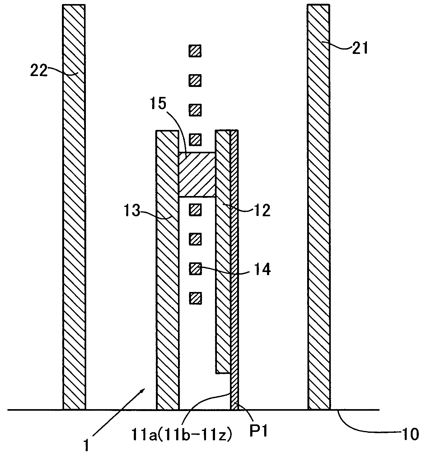
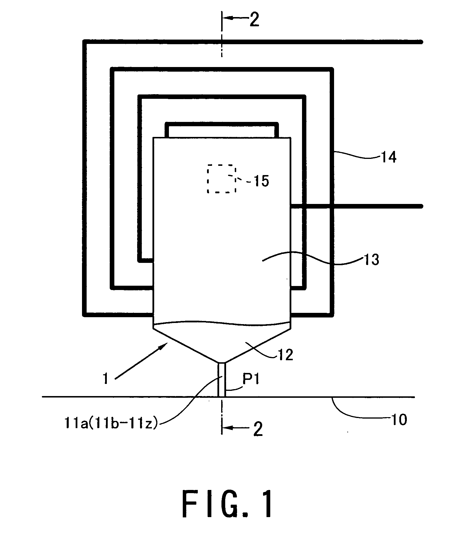
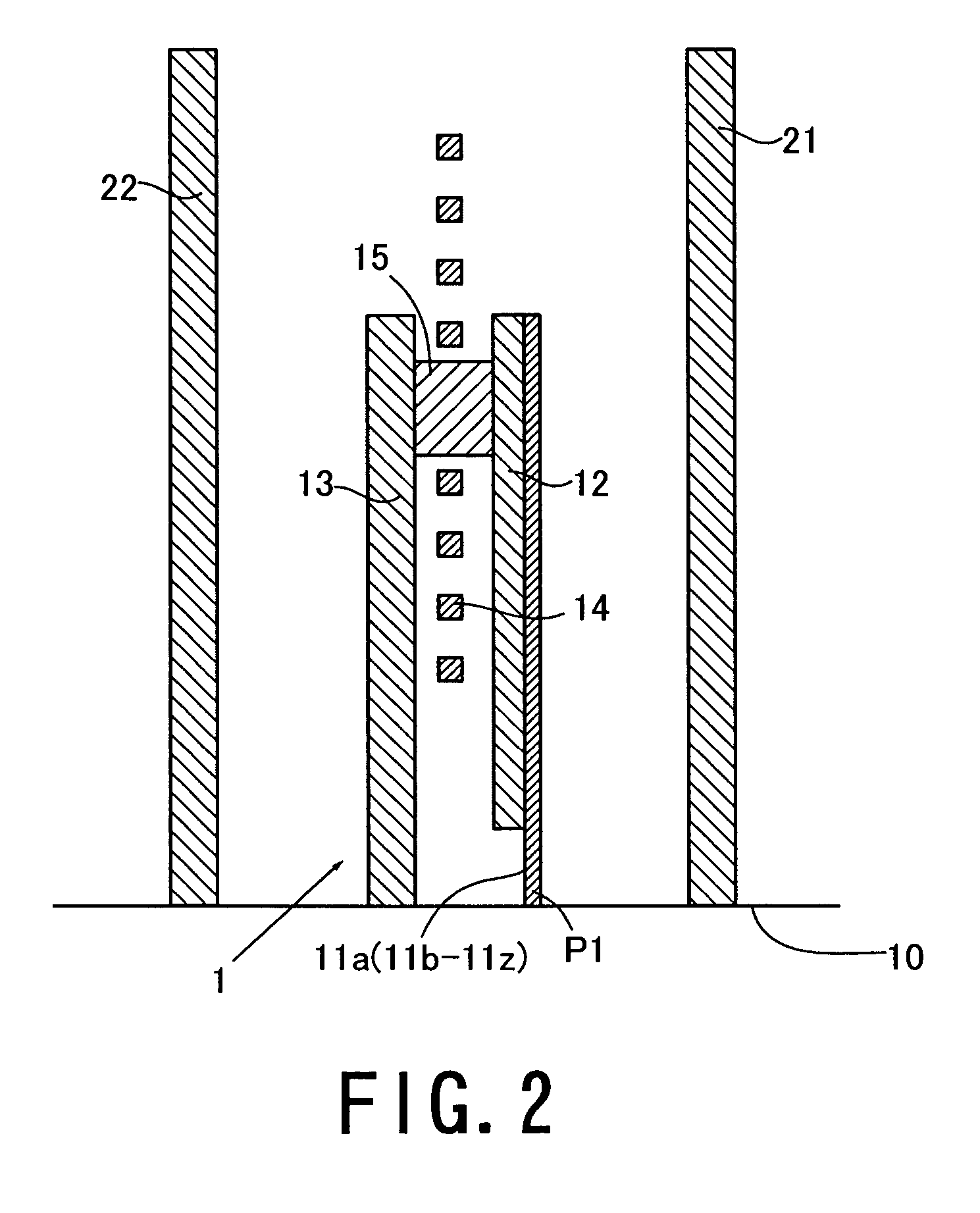
FIG. 1 is a plan view of the magnetic recording element according to the present invention, FIG. 2 is a sectional view taken along line 2-2 in FIG. 1 and FIG. 3 is a view of an end surface of the perpendicular magnetic recording element shown in FIGS. 1 and 2. While the magnetic recording element according to the present invention is most often adopted in a flying-type thin film magnetic head, its application is not limited to floating-type thin film magnetic heads and it may be utilized in a wide range of applications for high-density recording in the field of magnetic recording.

A recording element unit 1 is magnetically shielded with a first shield film 21 and a second shield film 22 arranged over a distance from each other. An insulating film constituted of, for instance, a metal oxide or an organic insulating material is arranged over the blank area surrounding the recording element unit 1, the first shield film 21 and the second shield film 22. The perpendicular magnetic recor...


PUM


Abstract

The soft magnetic film takes its hard axis along the direction in which a magnetic field is generated and its easy axis along a direction perpendicular to the direction of the writer magnetic field. The magnetic bias film applies a magnetic bias along the easy axis to the soft magnetic film.

Description

TECHNICAL FIELD The present invention relates to a perpendicular magnetic recording element, a magnetic head, a magnetic head device and a magnetic recording / reproducing apparatus. BACKGROUND OF THE INVENTION In order to improve the recording capacity of a hard disk drive (hereafter referred to as an HDD), the track density must be increased by reducing the magnetic pole width at the magnetic writer head and, at the same time, the recording capability must be improved by utilizing a material having a high saturation magnetization. When a perpendicular magnetic recording method is adopted, a high coercivity must be assured in the medium in order to improve the recording resolution. In addition, in order to assure the desired overwrite characteristics in the writer head, the writer magnetic pole must be constituted by using a material with a high saturation magnetization such as an FeCo-system material, a CoNiFe ternary alloy film, FeC or FeN. However, while the use of the type of ...

Claims


Application Information

Patent Timeline
IPC IPC(8): G11B5/31G11B5/127
CPCG11B5/127
Inventor HIRATA, KEINOGUCHI, KIYOSHIMINO, TETSUYAROPPONGI, TETSUYA
Owner TDK CORPARATION
Learn More