
Wastewater treatment system

a wastewater treatment system and wastewater technology, applied in the direction of multi-stage water/sewage treatment, other chemical processes, separation processes, etc., can solve the problems of unfavorable environmental protection, unfavorable environmental protection, and undesirable overtreatment of wastewater with chlorine, so as to achieve the effect of maximum “swirling” effect of water and negative pressur

Inactive Publication Date: 2005-01-20
S02 SOLUTIONS
View PDF12 Cites 14 Cited by
  • Summary
  • Abstract
  • Description
  • Claims
  • Application Information

AI Technical Summary

Benefits of technology

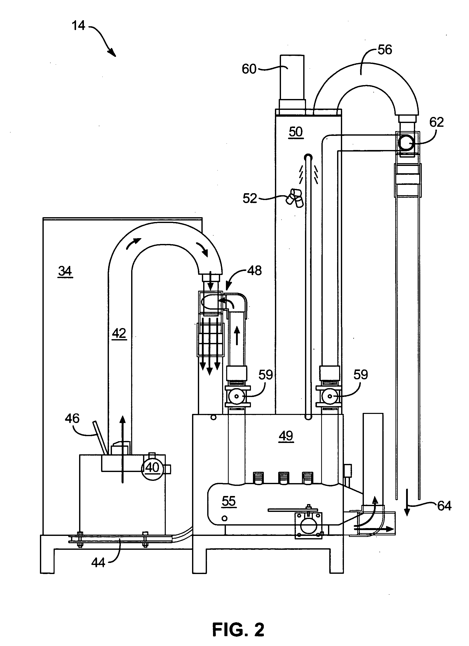
[0014] In one embodiment, a negative pressure source downstream from the hot SO2 gas outlet draws SO2 gas out of the burning chamber and combustion air into the burning chamber. The negative pressure source may be a venturi, an air amplifier, or a water aspirator. In one embodiment, the water inlet port on the aspirator may be offset to maximize the “

Problems solved by technology

It is undesirable to under treat the wastewater stream because active bacteria will thus remain in the wastewater stream.
It is also undesirable to over treat the wastewater with chlorine because a residual chlorine level in the wastewater stream will be detrimentally high.
Additionally, the chlorine or other treatment fluid is wasted and additional chemical is typically needed to neutralize the excess chlorine.
Wastewater treatment facilities additionally suffer financially from the unnecessary use of excess chlorine and chlorine neutralizing chemicals, such as sulfur dioxide when the chlorination / de-chlorination process is not operating optimally.
When compressed sulfur dioxide gas is used to neutralize the excess chlorine, there is not only its cost but also the danger associated with its use.
However, these generators are not adapted for wastewater treatment nor do they typically include the necessary safety systems that would be required.

Method used


Image

  • Wastewater treatment system
  • Wastewater treatment system
  • Wastewater treatment system

Examples


Embodiment Construction

[0032] It will be readily understood that the components of the present invention, as generally described and illustrated in the Figures herein, could be arranged and designed in a wide variety of different configurations. Thus, the following more detailed description of the embodiments of the system and method of the present invention, as represented in FIGS. 1 through 9, is not intended to limit the scope of the invention, as claimed, but is merely representative of the presently preferred embodiments of the invention.

[0033] In the following description, like reference characters designate like or corresponding parts throughout the several views. Also in the following description, it is to be understood that terms such as “forward,”“rearward,”“left,”“right,”“upward,”“downward,” and the like are words of convenience and are not to be construed as limiting terms.

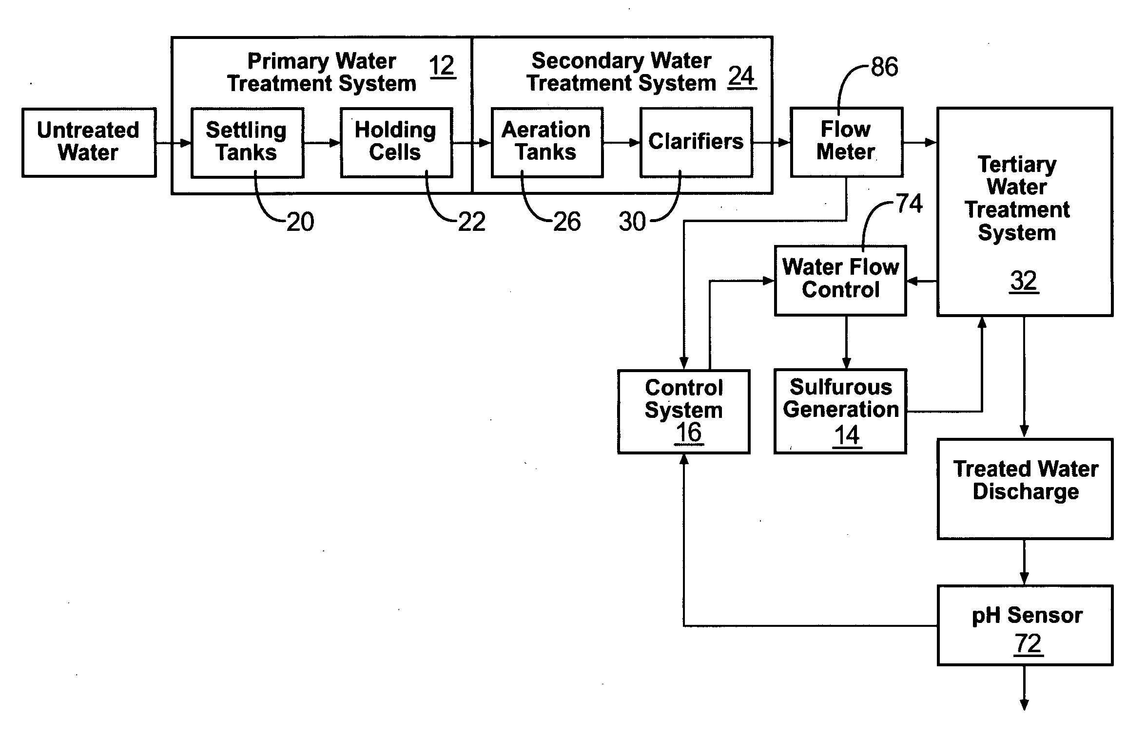
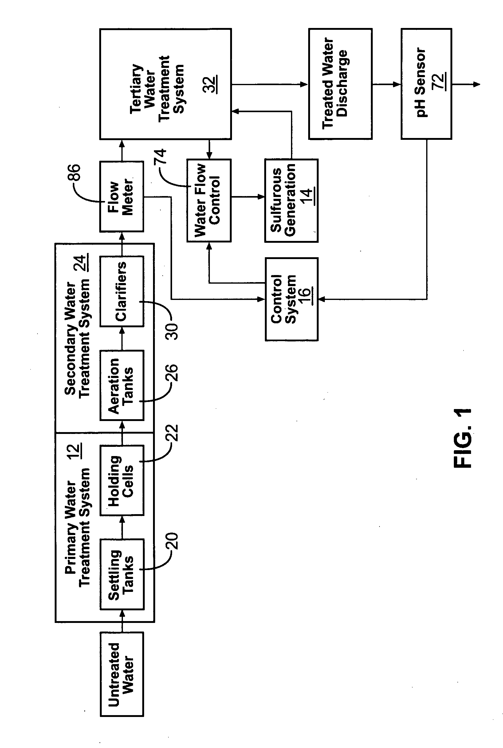
[0034] Referring to FIG. 1, a water treatment system is shown constructed according to the present invention. The water ...


PUM

PropertyMeasurementUnit
Lengthaaaaaaaaaa
Lengthaaaaaaaaaa
Weightaaaaaaaaaa

Abstract

A water treatment system for treating water. The water treatment system includes a primary water treatment station and a solid-based sulfurous generator downstream from the primary water treatment station for producing aqueous sulfurous acid for further treatment of the water. In one embodiment, the solid-based sulfurous generator includes a hydraulic air inlet shut off valve safety system for automatically reducing the combustion air to the sulfurous generator when water is not delivered to the solid-based sulfurous generator. Also, in one embodiment, the water treatment system includes a control system that monitors the pH of the treated water to control the water flow rate through the solid-based sulfurous generator to achieve the desired concentration of sulfurous acid in the water being treated.

Description

RELATED APPLICATIONS [0001] This application claims priority to co-pending U.S. Provisional Patent Application Ser. No. 60 / 452,515 filed on Mar. 6, 2003.BACKGROUND [0002] 1. Field of the Invention [0003] The present invention relates generally to water treatment systems and, more particularly, to a water treatment system which utilizes aqueous sulfurous acid produced by a solid sulfur-based sulfurous generator for further treatment of the water. [0004] 2. Description of the Prior Art [0005] In wastewater treatment facilities, a main stream of wastewater typically is treated with a chlorine-containing compound, such as sodium hypochlorite, to neutralize bacteria in the wastewater stream. It is undesirable to under treat the wastewater stream because active bacteria will thus remain in the wastewater stream. It is also undesirable to over treat the wastewater with chlorine because a residual chlorine level in the wastewater stream will be detrimentally high. Additionally, the chlorine...

Claims


Application Information

Patent Timeline
IPC IPC(8): C02F1/00C02F1/68C02F1/76
CPCC02F1/008C02F1/687C02F2209/06C02F2303/185C02F2209/40C02F2303/18C02F2209/29
Inventor WEBB, JAMES
Owner S02 SOLUTIONS
Learn More