
Vented insulated building

a technology of insulated buildings and vents, applied in the field of building construction, can solve the problems of not eliminating or significantly reducing the potential for condensation not preventing condensation on these cool surfaces, and reducing the amount of moisture in the space between exterior sheathing and interior walls, so as to reduce the risk of resulting damage, and avoid the effect of environmental degradation and health problems

Inactive Publication Date: 2005-01-20
CORWIN THOMAS N
View PDF35 Cites 9 Cited by
  • Summary
  • Abstract
  • Description
  • Claims
  • Application Information

AI Technical Summary

Benefits of technology

[0007] The invention provides improved building construction techniques and building structures that eliminate or substantially reduce condensation at exterior building walls, thereby preventing conditions that would promote mold growth, and thereby avoiding the resulting damage, environmental degradation and health problems associated with mold growth. The improved building construction techniques and structures of this invention also help prevent accumulation of toxic volatile organic compounds off-gassed from building materials within spaces between exterior sheathing and interior walls of buildings, thus minimizing health problems associated with these toxic compounds.
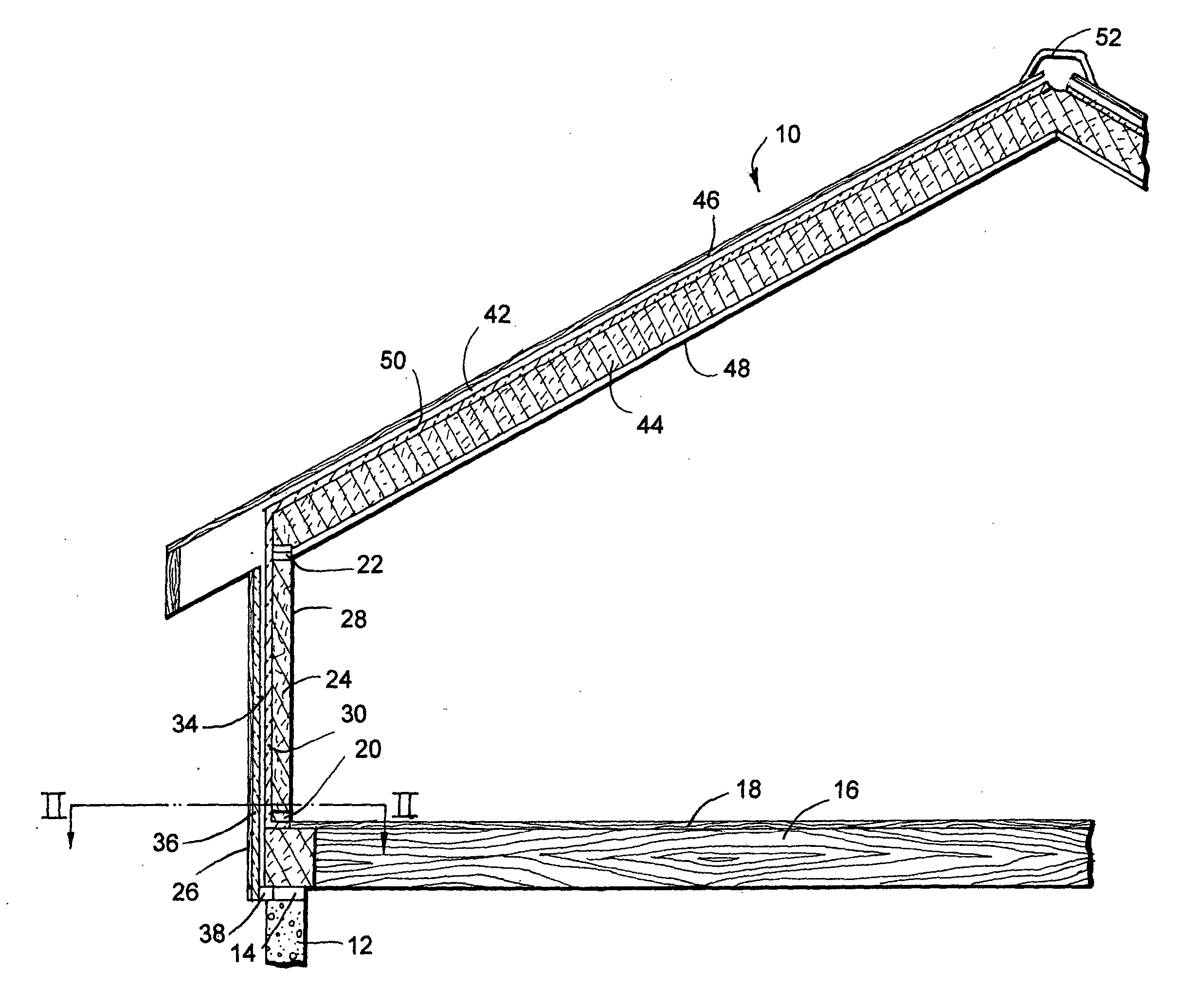
[0008] In accordance with an aspect of this invention, a building having enveloping air spaces that allow natural convection of air in exterior wall structures and roof structures is provided. The building includes an exterior wall structure having an exterior sheathing, an interior wall, and at least one layer of thermal insulation material between the exterior sheathing the interior wall. The layer of thermal insulation material is spaced away from the exterior sheathing to provide a wall air gap between the insulation and the exterior sheathing. The building also includes a roof structure having a roof deck, an interior ceiling, and a layer of thermal insulation material between the roof deck and interior ceiling. The layer of thermal insulation material is spaced away from the roof deck to provide a roof air gap between the layer of thermal insulation material and the roof deck. The structure also includes a roof vent to allow air to flow freely from the roof air gap to an outside space. The building structure is configured so that the wall air gap is in fluid communication with the roof air gap. An air ventilation grid is located at the lower end of the wall air gap. The air ventilation grid has a plurality of openings that are sufficiently small to prevent insects from entering the wall air gap, but sufficiently large to allow outside air to freely enter into the wall air gap, whereby air is allowed to freely flow by natural convection upward from the outside through the ventilation grid, upwardly through the wall air gap, upwardly along the roof air gap, and out the roof vent. The structure eliminates stagnation of air within spaces defined between exterior building surfaces and interior building surfaces, thereby eliminating or very substantially reducing moisture condensation within these spaces.

Problems solved by technology

A problem with conventional building construction, especially residential buildings, is that moisture tends to condense in the space between the exterior sheathing and the interior wall.
However, they do not eliminate or significantly reduce the potential for condensation between exterior sheathing and interior walls.
Regulating conditions within the interior living spaces of a building does not prevent air trapped between exterior sheathing and interior walls from contacting surfaces at or below the dew point temperature of the trapped air, and therefore does not prevent condensation on these cool surfaces.
Unfortunately, many building materials contain organic materials that molds may use as a source of food.
It is generally well accepted that the only practical way of preventing mold growth in buildings is to prevent water leaks and condensation from accumulating on building materials and / or other materials that can provide nourishment to the molds, since it is practically impossible to prevent the microscopic mold spores from contacting building materials and / or eliminate food sources from building materials.
Even relatively small amounts of mold can release toxic chemicals that cause dry coughs, runny noise, rashes and fatigue.
Sensitive individuals may experience more serious health problems, such as headache, nosebleed, dizziness, allergic reactions, asthma and / or other respiratory problems.
High levels of mold contamination can cause very serious chronic and acute health problems such as neurological disorders, brain damage, autonomic dysfunction, hypotension and / or cancer.
Another problem that frequently occurs in residential buildings, especially in the vicinity of a sky light or roof window, is the formation of ice dams.
Heat from a hot spot on the roof can cause snow to temporarily melt and re-solidify at a down slope colder spot on the roof, thereby forming an ice dam which can cause water to pool up slope of the ice dam.
However, sloped residential roofs are not typically watertight.
As a result, any standing water, such as a pool of water adjacent an ice dam, can leak under and between roof tiles into the building causing damage and / or promoting mold growth.
This causes the air between the rafters to become stagnated and overheated, thereby allowing formation of ice dams and resulting water damage.
However, this results in weakening of the structure and is extremely labor intensive.
A further problem with current building construction techniques is that they tend to allow toxic volatile organic compounds (VOCs) that are off-gassed from construction materials, such as flooring, paints, varnishes, cabinets, etc., to accumulate in living spaces and in spaces between exterior sheathing and interior walls.
Toxic pollutants may continue to off-gas from various building materials for several years after they have been installed.
Accumulation of these off-gassed VOCs in stagnate air between exterior sheathing and interior wall panels may significantly extend this period thereby increasing health risks.

Method used


Image

  • Vented insulated building
  • Vented insulated building
  • Vented insulated building

Examples


Embodiment Construction

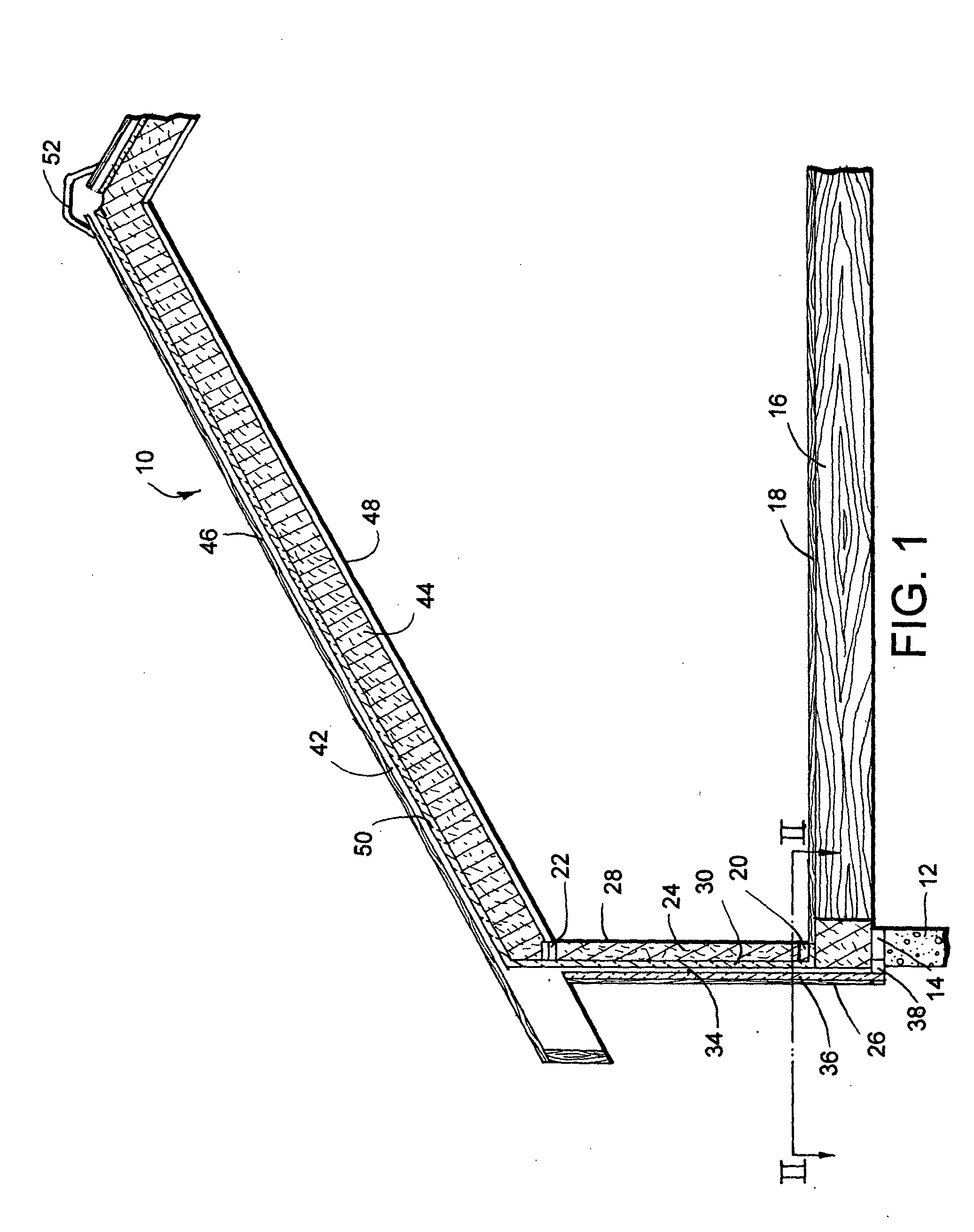
[0018] Shown in FIG. 1 is a schematic cross-sectional illustration of a building constructed in accordance with an aspect of the invention. Illustrated building 10 is constructed on a conventional foundation 12. Typically, lumber is fastened along the upper surface of the foundation 12 to form a continuous sill plate 14 onto which floor joists 16 are fastened in generally uniformly spaced apart parallel relationship. Plywood, orientated strand board, or other suitable panels are fastened over floor joists 16 to provide a floor deck 18. The building may be framed with lumber in a conventional manner with 2×4 bottom plates 20, 2×4 top plates 22 and 2×6 vertical studs 24.

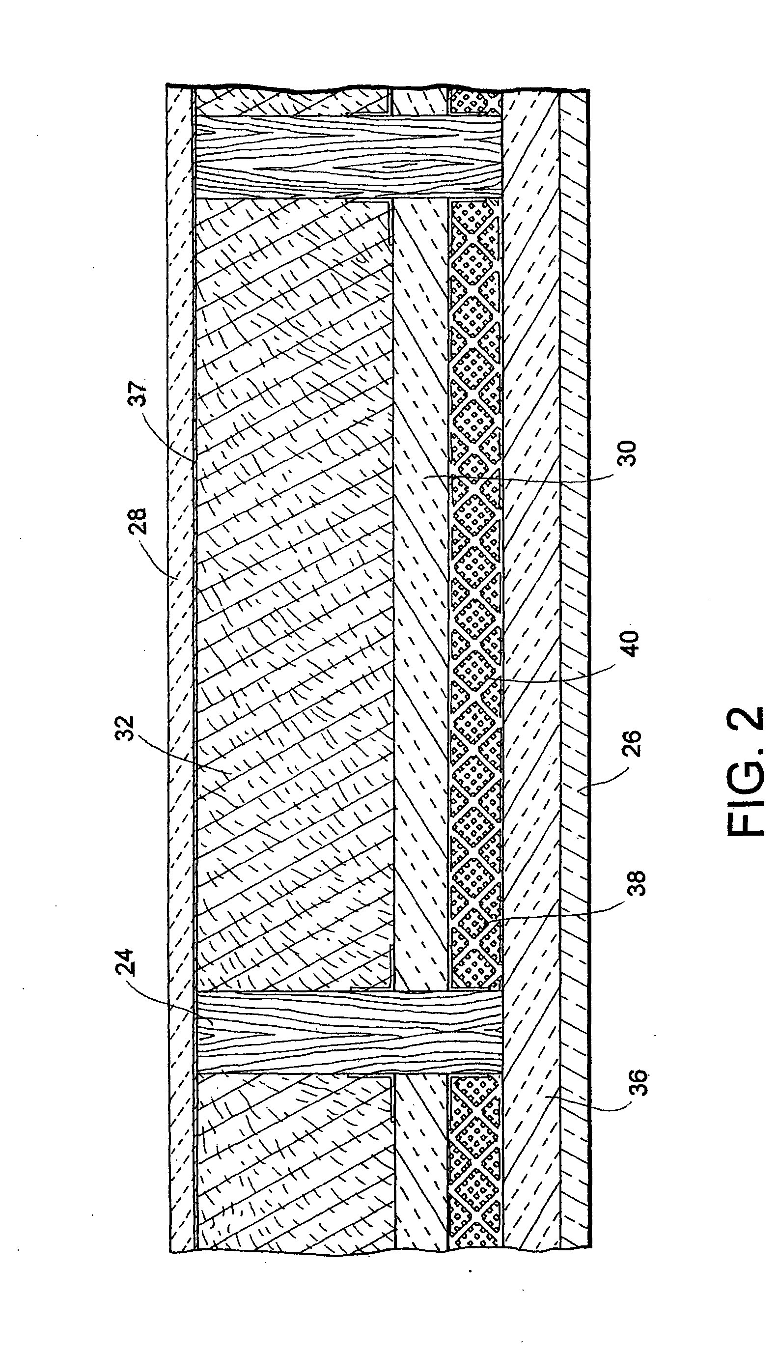
[0019] As is more easily seen in FIG. 2, insulation is disposed between exterior sheathing 36 and interior wall panel 28. Exterior facade material 26 is layered over exterior sheathing 36. In the illustrated embodiment, the insulation material comprises a one-inch polystyrene foam thermal insulation panel 30 having a ...


PUM


Abstract

An improved building structure that eliminates condensation at exterior building walls, thereby preventing mold growth and avoiding the damage, environmental degradation and health problems associated with mold growth includes enveloping spaces that allow natural convection of air in exterior wall structures and roof structures. An embodiment of the building structure includes an exterior wall structure defining an air gap between insulation and exterior sheathing, a roof structure defining an air gap between thermal insulation and a roof deck, the wall air gap and roof air gap being in fluid communication, a roof vent to allow air to flow to an outside space, and an air ventilation grid at the lower end of the wall air gap. The air ventilation grid includes openings that allow air to freely enter the wall air gap and flow upwardly by natural convection into the roof air gap and out of the roof vent.

Description

FIELD OF THE INVENTION [0001] This invention relates to building construction, and more particularly to insulated buildings having improved wall and roof ventilation that eliminate and / or substantially reduce problems associated with condensation at exterior wall surfaces, including growth of mold and mildew, problems associated with ice dam formation, and problems associated with accumulation of off-gas pollutants such as from carpeting, paints and other building materials. BACKGROUND OF THE INVENTION [0002] A problem with conventional building construction, especially residential buildings, is that moisture tends to condense in the space between the exterior sheathing and the interior wall. This can occur whenever the surfaces of the exterior sheathing are at or below the dew point temperature of the air between the exterior sheathing and the interior wall. It is believed that the improved air tight sealing techniques currently used in the building construction industry reduce the...

Claims


Application Information

Patent Timeline
Patent Type & Authority Applications(United States)
IPC IPC(8): E04B1/26E04B1/70E04D13/17
CPCE04B1/26F24F2007/004E04D13/17E04B1/7069
Inventor CORWIN, THOMAS N.
Owner CORWIN THOMAS N
Learn More