
Device for melting and remolding crayons

Inactive Publication Date: 2005-01-13
FERNANDEZ MARK S +1
View PDF14 Cites 21 Cited by
  • Summary
  • Abstract
  • Description
  • Claims
  • Application Information

AI Technical Summary

Benefits of technology

[0008] The toy molding machine comprises a stationary melting chamber to minimize the chance that molten material may be unexpectedly discharged from the melting chamber, either accidentally or as a result of poor judgement. An electrical heating element conducts heat to the melting chamber, and a warning light glows when electrical current flows to the heating element. A mold appropriate for forming a three-dimensional crayon or some other interesting object is provided in an enclosed area to which the child's access is intermittently restricted for safety reasons. For example, a remotely operated gate may alternately permit and prevent flow between the melting chamber and the mold. The child's access to the mold is restricted during those periods when the gate is permits flow.
[0009] Some embodiments of the toy molding machine include a housing that substantially surrounds the melting chamber and the molding area to isolate the child from hot surfaces. The melting chamber is charged from outside of the housing through a filling port. A door provides access to the mold when the door is in an open position and prevents access to the molding area when the door is in a closed position.
[0010] After an on / off switch to an electrical power supply is activated, a thermostatic switch controls the temperature of the melting chamber. Various interlocks and shutdowns can also be incorporated to enhance the safe operation of the toy molding machine. For example, the door and the gate can be linked together, mechanically or otherwise, so that the door to the restricted area cannot be opened while the gate permits flow to the mold. Other examples include a high-temperature switch, a tilt switch or a door switch to interrupt the supply of electrical power to the heating element under certain circumstances.

Problems solved by technology

The child's access to the mold is restricted during those periods when the gate is permits flow.

Method used


Image

  • Device for melting and remolding crayons
  • Device for melting and remolding crayons
  • Device for melting and remolding crayons

Examples


Embodiment Construction

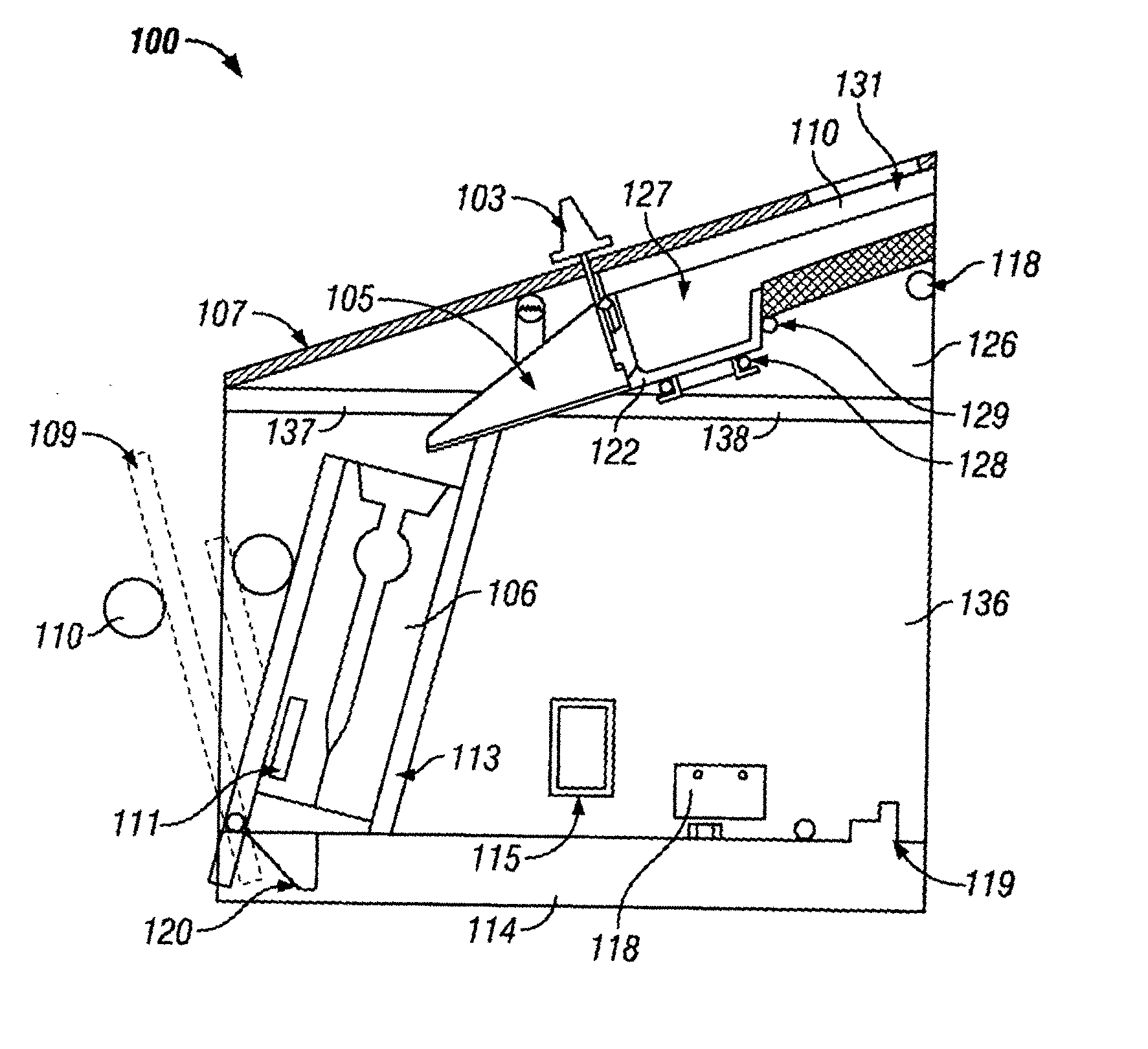
[0015] In a preferred embodiment, the invention is a toy molding machine, such as crayon molder 100 depicted in FIGS. 1-2. FIG. 1 illustrates housing 133, which includes sidewall 102, cover 107 and door 109. Housing 133 is a unitary injection-molded plastic piece. Housing 133 substantially isolates a user from internal components that may be hot or electrified at some time during the molding process. Materials for melting, such as crayon pieces, are fed through a filling port 101 from the outside of housing 133 into fill chute 139. Splash guards 131 extend from chute 139 in order to prevent molten material from contacting a user. Preferably, chute 135 and splash guards 131 are composed of molded silicone rubber, shaped to receive melting pot 127. Gate 104 is a silicon robber valve plug, which controls the flow of molten material within molder 100, is operated from the outside of housing 133 by means of regulator 103. If and only if certain safety conditions are established, door 109...


PUM

PropertyMeasurementUnit
Temperatureaaaaaaaaaa
Poweraaaaaaaaaa
Flow rateaaaaaaaaaa

Abstract

A device suitable for use by children which recycles broken crayons and other materials by melting and molding. A stationary melting pot securely retains the charge material during heating. A housing substantially surrounds the melting pot and an associated mold chamber to isolate young operators from all heated surfaces. The melting pot is charged from outside of the housing by use of a filling port. A remotely operated gate controls the flow from the melting pot to a mold. A door provides access to the mold when open and prevents access to the mold chamber when closed. A warning light glows when a heating element for the melting chamber is energized. Various safety switches interrupt power to the heating element if certain conditions are not met.

Description

TECHNICAL FIELD OF THE INVENTION [0001] The invention relates to toy molding devices for recycling solids having a relatively low melting temperature or melting range. BACKGROUND OF THE INVENTION [0002] Molding devices for making toys have been popular with children for generations. They can be used to melt and mold waxes, resins, thermoplastics or certain metal alloys to make interesting objects. However, the melting and molding process typically requires a heat source and relatively high temperatures. Although nothing can be completely safe, previous molding toys have not been as simple or as safe as today's parents desire. [0003] U.S. Pat. No. 3,063,109, issued to Rapaport, describes a toy casting machine for melting metal which includes an electrically heated melting chamber. The Rapaport patent reports that the toy casting machine is safe because the melting chamber is covered during operation. However, the path of molten material from a discharge spout to the mold is freely ac...

Claims


Application Information

Patent Timeline
IPC IPC(8): A63H33/00B29C31/04B29C39/00B29C39/02B29C39/24B29C39/44B29C67/24B43K19/16
CPCA63H33/001B29C31/042B29C39/003B29C39/02B29C39/24Y10S425/057B29C67/241B29C2037/94B29K2105/26B29L2031/5218B43K19/16B29C39/44
Inventor FERNANDEZ, MARK S.STORTROEN, ANDY O.
Owner FERNANDEZ MARK S
Learn More