
Matched texture filter design for rendering multi-rate data samples

a texture filter and data sample technology, applied in the field of graphics systems, can solve the problems of undesirable artifacts, variable sampling rate or other non-standard graphics processes, and the filtering algorithm of the various texture filter algorithms does not address the problem of variable sampling rate or other non-standard graphics processes, and conventional systems do not provide a texture filter that varies the filter

Inactive Publication Date: 2005-01-13
S3 GRAPHICS
View PDF34 Cites 7 Cited by
  • Summary
  • Abstract
  • Description
  • Claims
  • Application Information

AI Technical Summary

Benefits of technology

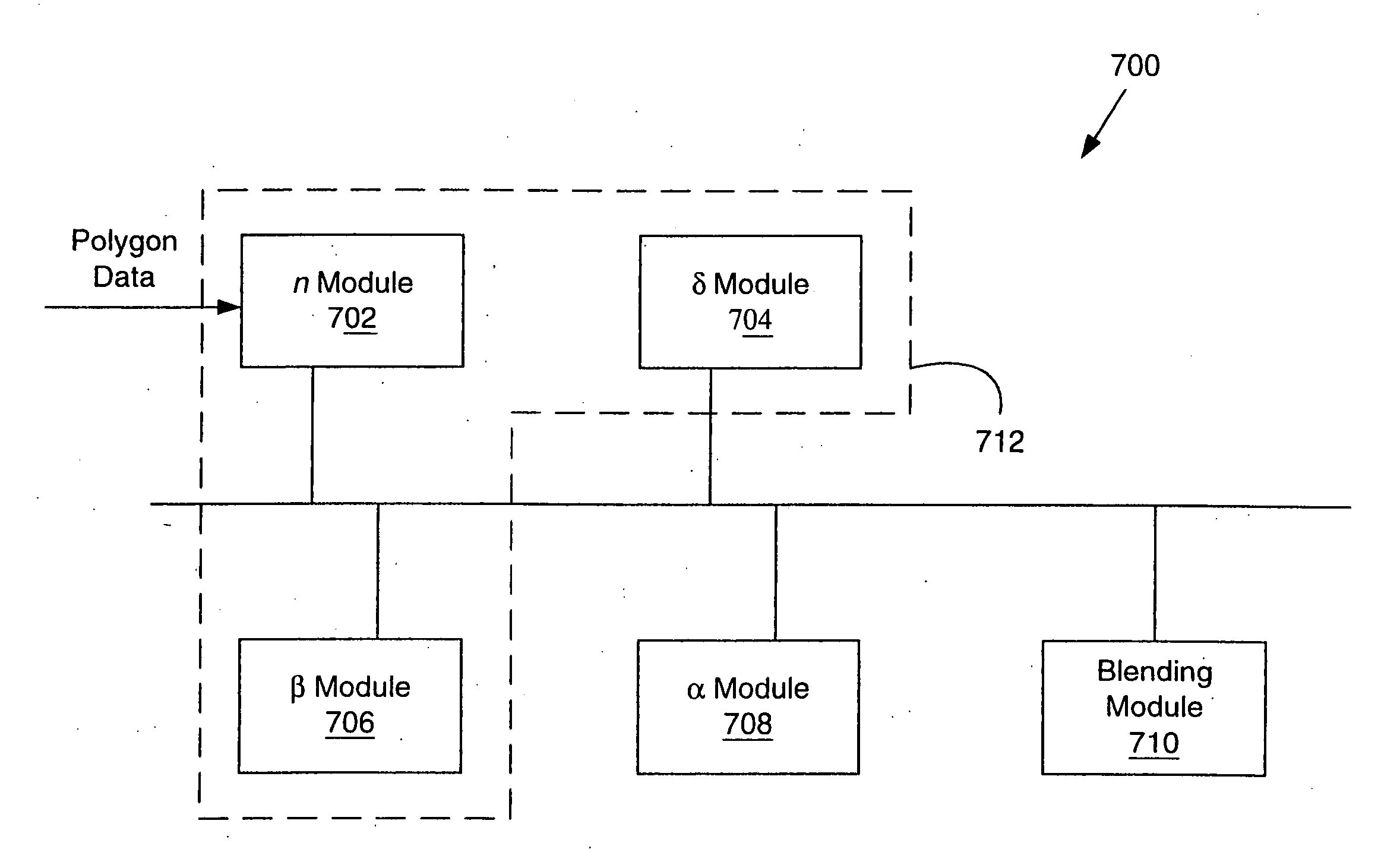
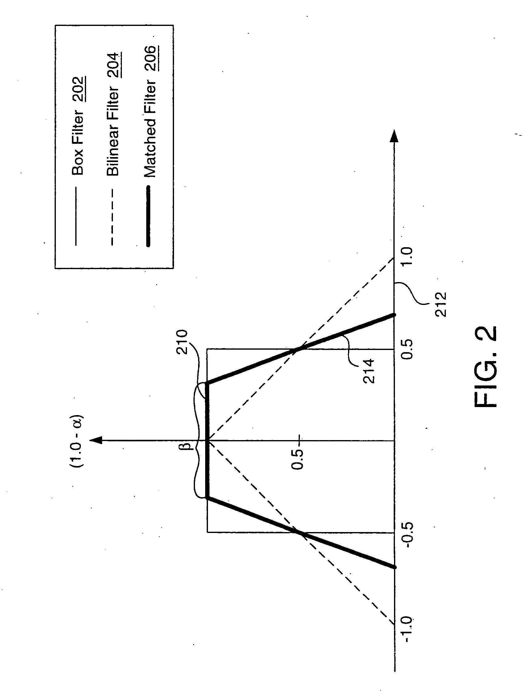
The present invention provides in various embodiments a texture filter that takes into account the sampling rate and the non-linear mapping between screen coordinates and texture coordinates. In particular, these embodiments of the present invention provide a matched texture filter that continuously changes the pass band-stop band characteristics based upon the rate of sampling of polygon data and the extent of perspective warping introduced by the non-linear screen-to-texture mapping function. The matched texture filter is capable of changing so that after post-filtering, the resulting filter characteristic effectively matches the characteristics of a filter used for coarse sampling.
In a further embodiment, the variation of the filter characteristics between the various filter modes (e.g., bilinear filter, trilinear filter, point sample filter, etc.) is preferably continuous. By continuously varying texture filters between two modes, banding in images and artifacts normally visible during animation are eliminated.

Problems solved by technology

These various texture-filtering algorithms do not address the problem of variable sampling rate or other non-standard graphics processes.
Otherwise, the effective filter characteristics will not be consistent over the entire scene, resulting in undesirable artifacts.
Conventional systems do not provide a texture filter that varies the filter characteristics in response to, for example, the rate of sampling and the extent of texture warping.
Such deficiencies of conventional systems lead to images that are generated with undesirable artifacts.

Method used


Image

  • Matched texture filter design for rendering multi-rate data samples
  • Matched texture filter design for rendering multi-rate data samples
  • Matched texture filter design for rendering multi-rate data samples

Examples


Embodiment Construction

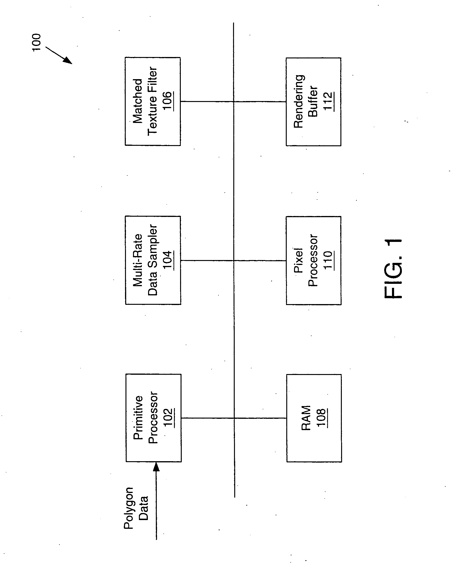
FIG. 1 is a block diagram of an exemplary system 100 for performing the texture filtering operations of the present invention. The system 100 is typically implemented in a graphics processing system within a computer or similar processing device. The system 100 includes a primitive processor 102, a multi-rate data sampler 104, a matched texture filter 106, RAM 108 for storing textures, a pixel processor 110 and a rendering buffer 112.

The primitive processor 102, which may be a triangle processor, typically receives the three-dimensional geometry elements (e.g., triangles or other graphic primitives) and processes the data describing the size, shape, position, and other relative characteristics of the graphics primitives. In some cases, the primitive processor 102 is also capable of generating edge functions of the primitives. These primitives may be defined in three-dimensions using Euclidian coordinates or in four-dimensions using homogenous coordinates, and subsequently, projecte...


PUM


Abstract

A method and apparatus for texture filtering is provide wherein a filter select module is adapted to select a filtering mode based upon a sampling rate of polygon and texture data. The filter mode is selected by determining the filter characteristics of the selected filtering mode based upon the sampling rate and a degree of warping per texture coordinate. A texture reconstruction filter characteristic is morphed based upon the input polygon and texture data so that, after subsamples are aggregated, an effective filter characteristic matches the texture reconstruction filter characteristic of a texture reconstruction filter used for coarse sampling. Subsequently, a texel blending module computes texel blending factors based on the filtering mode determined by the filter select module.

Description

BACKGROUND OF THE INVENTION 1. Field of the Invention The present invention relates generally to graphics systems, and more particularly to texture filtering for 3D graphics with screen pixel digitization at variable sampling rates. 2. Description of the Background Art A texture is a digital image, typically rectangular in shape, having a (u, v) coordinate space. The smallest addressable unit of a texture is a texel, which is located at a particular coordinate in the (u, v) coordinate system. In a texture mapping operation, a texture is mapped to the surface of a graphical model as the model is rendered to create a destination image. In the destination image, pixels are located at particular coordinates in the (x, y) coordinate system. In texture mapping, data is sampled from the texture to compute an intensity value for a pixel in the destination image. The sampled texels for a given pixel are typically identified by mapping a point in the destination image into the texture. T...

Claims


Application Information

Patent Timeline
Patent Type & Authority Applications(United States)
IPC IPC(8): G06T11/00
CPCG06T11/001
Inventor VIJAYAKUMAR, BASKARANIOURCHA, KONSTANTINE I.
Owner S3 GRAPHICS
Learn More