
Heating systems and methods

Inactive Publication Date: 2005-01-13
ITHERM TECH LP
View PDF32 Cites 38 Cited by
  • Summary
  • Abstract
  • Description
  • Claims
  • Application Information

AI Technical Summary

Benefits of technology

The high frequency harmonics may be used to vary the inductive heating power. The harmonics may enhance a relative proportion of inductive heating, compared to resistive heating, of the heater coil. The high-frequency harmonics may enable use of a lower fundamental (or root) frequency supply current (e.g., line frequency of 50-60 Hz). The effective frequency of the current pulse, based on a combination of the root and harmonic frequency components, and their amplitudes, may enhance the lifetime of the heater coil in particular applications and / or enable more rapid heating of the coil.
According to various implementations, the method steps may include simultaneous, discontinuous, intermittent and / or alternating periods of heating, cooling, and / or temperature control; adjusting the energy content of the current pulse signals with respect to amplitude, pulse width and / or frequency spectrum; and / or providing a cooling mechanism (cooling medium or heat sink) to withdraw heat from the article being heated. Particular structures are disclosed for accomplishing these method steps. Various embodiments of such heating systems and methods may provide one or more benefits such as more uniform heating, reduced thermal gradients, reduced thermal stresses, reliable high temperation operation, compact design, shorter cycle time, and reduced heat-up time.

Problems solved by technology

The air gap and cooling requirements increase the complexity and cost of the heating system.
They also reduce the strength (structural integrity) of the apparatus, which can be critical in applications where pressure is applied, e.g., a compression mold.
However, without cooling, the coil is subject to failure (melting or burn out at elevated temperatures).
Traditional inductive heating systems do not utilize more highly resistive (e.g., NiCr) coils, because the enhanced resistive heating of the coil would make coil cooling even more difficult, requiring still larger cooling channels and / or lower cooling temperatures, each of which results in greater energy consumption and cost.
Furthermore, a resistive load cannot be driven by a traditional inductive power supply.

Method used


Image

  • Heating systems and methods
  • Heating systems and methods
  • Heating systems and methods

Examples


second embodiment

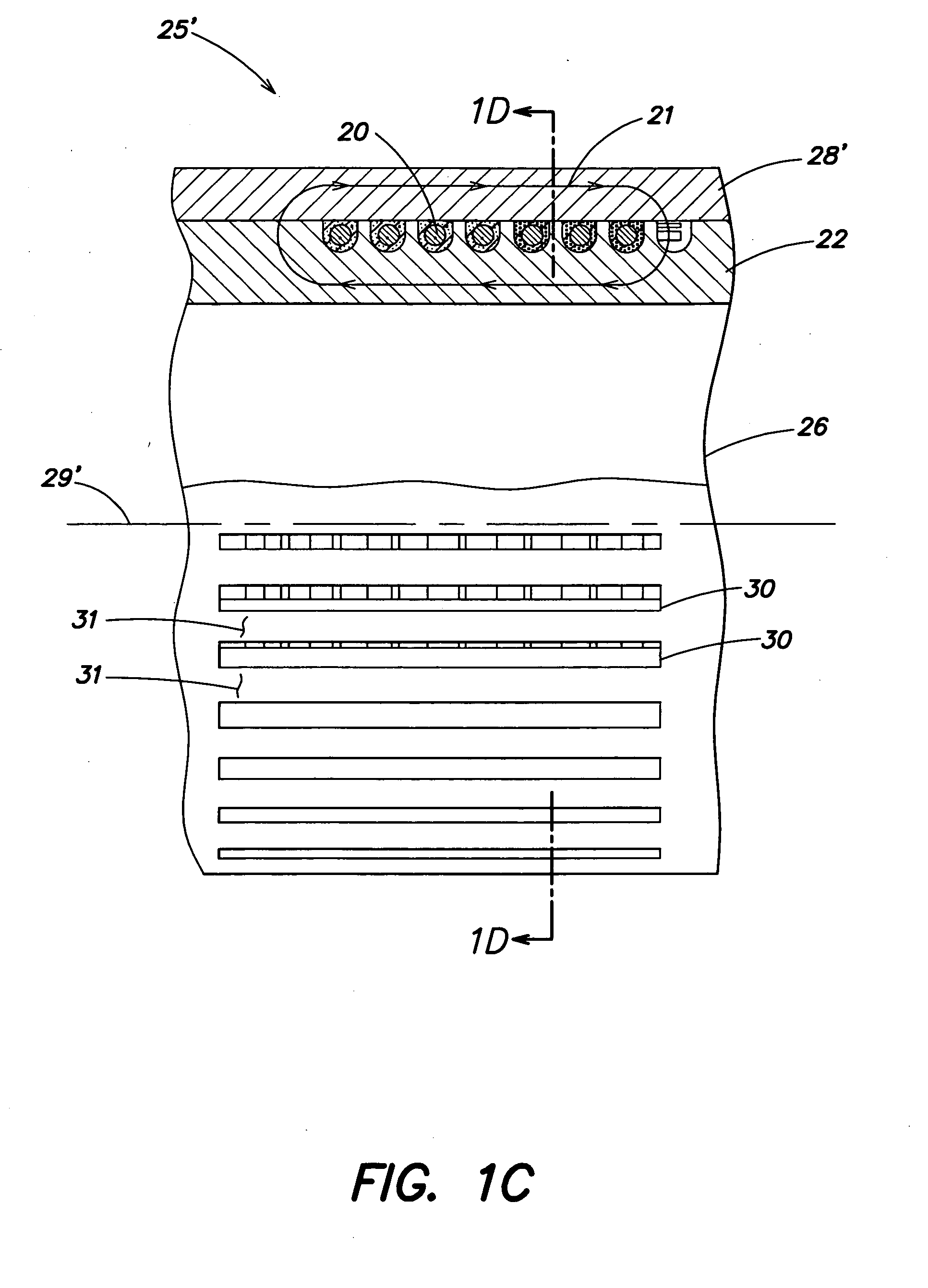
a similar heating system is shown in FIGS. 1C-1D. This modified system 25′ includes a modified yoke 28′ having elongated hollow portions or slots 30, and between the slots, elongated solid portions or ribs 31; the slots 30 and ribs 31 are disposed substantially parallel to the core / yoke center line 29′. The slots 30 are at right angles to the loops of coil 20 wrapped around core 22. The slots 30, which are effectively air gaps, create discontinuities or restrictions in the eddy currents 32 within the yoke 28′, as shown in FIG. 1D (a sectional view taken along section line 1D-1D in FIG. 1C). In contrast, there are no slots in core 22 restricting the eddy currents 33 in the core 22. This arrangement results in preferential inductive heating in the core 22, rather than the yoke 28′; this is desirable when the ultimate article to be heated is a material in the passage 26 of the core 22. Thus, a greater percentage of the power delivered to the heating system is transmitted to the article...


PUM

PropertyMeasurementUnit
Fractionaaaaaaaaaa
Fractionaaaaaaaaaa
Fractionaaaaaaaaaa

Abstract

Heating systems and methods for inductive heating or a combination of resistive and inductive heating. A heater coil is inductively coupled to an article and a current signal is supplied to the heater coil. The heater coil generates a magnetic flux, based on the applied current signal, for inductively heating the article. Current pulses of a certain profile are used to enhance the rate, intensity and / or power of inductive heating delivered by the heating element or coil and / or to enhance the lifetime or reduce the cost of the inductive heating system.

Description

FIELD OF THE INVENTION This invention relates to heating systems and methods which include, in various implementations, utilizing inductive heating or a combination of resistive and inductive heating; furthermore, the heating may be localized (directed to particular areas), and / or the heating may be continuous or intermittent. BACKGROUND OF THE INVENTION It is common practice to inductively heat a cylinder or tube of a ferromagnetic (high magnetic permeability) material, such as steel, by an induction (eddy) current. The eddy current is induced in the ferromagnetic material by an applied magnetic flux, and the magnetic flux is generated by passage of an alternating current through one or more heater coils disposed around the cylinder or tube. This method of inductive heating can be adapted to various other types of materials, work pieces and loads, including fluid, semisolid or solid materials (e.g., molten steel or magnesium filled and non-filled polymers, billets and ceramics). ...

Claims


Application Information

Patent Timeline
IPC IPC(8): H05B6/04H05B6/06
CPCH05B6/04H05B6/062H05B6/1209Y02B40/126H05B2206/024Y02B40/123H05B6/1245Y02B40/00H05B6/06H05B6/02
Inventor KAGAN, VALERY
Owner ITHERM TECH LP
Learn More