Combustion-powered driving tool
a technology of driving tool and combustion engine, which is applied in the direction of manufacturing tools, stapling tools, nailing tools, etc., can solve the problems of unsatisfactory driving force, motor and fan have not yet reached the rotational speed capable of producing a sufficient driving force, and the method is expensive, so as to achieve the effect of convenient use, convenient operation and convenient us
- Summary
- Abstract
- Description
- Claims
- Application Information
AI Technical Summary
Benefits of technology
Problems solved by technology
Method used
Image
Examples
first embodiment
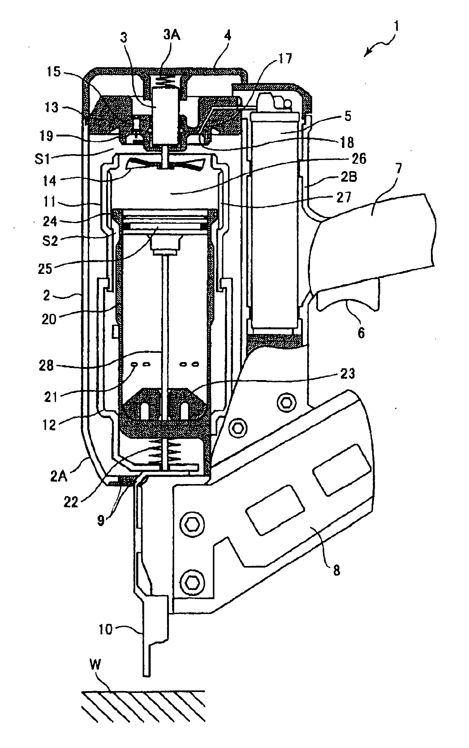
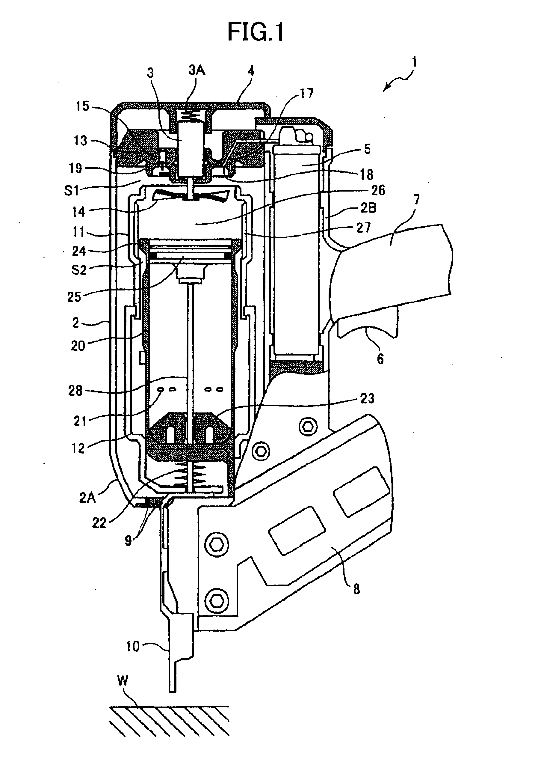
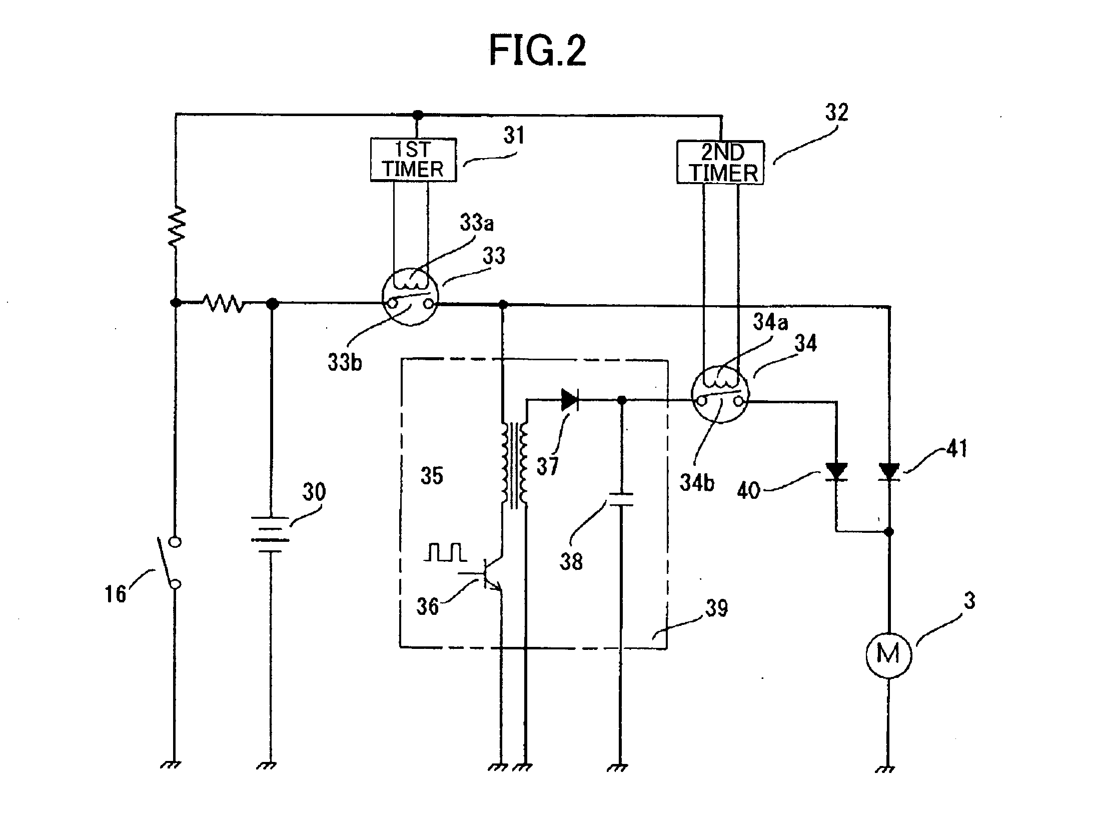
[0038] Next, a first embodiment will be described while referring to FIGS. 1, 2 and 3A-3B, wherein the combustion-powered tool of the present invention is applied to a combustion-powered, fastener-driving tool. In the following description, it is assumed that the tool is held in an orientation in which nails are fired toward a downward direction.
[0039] A combustion-powered, fastener-driving tool 1 has a housing 2 that forms an outer framework. The housing 2 includes a main housing section 2A and a tank chamber 2B provided alongside the main housing section 2A in the lengthwise direction. An intake hole (not shown) is formed in the top of the main housing section 2A, while an exhaust hole (not shown) is formed in the bottom of the same.
[0040] A head cover 4 is mounted on the top of the main housing section 2A. A gas tank 5 containing flammable gas is removably accommodated in the tank chamber 2B. A handle 7 extends outward from the tank chamber 2B. The handle 7 is provided with a tr...
second embodiment
[0057] A combustion-powered, fastener-driving tool according to the invention will be described while referring to FIGS. 4 through 9 where like components and parts as appeared in FIG. 1 are designated by like reference numerals and duplicate description thereof is omitted. In FIG. 4, reference numerals 251 and 201 designate a trigger switch and a push switch that function similar to the trigger switch 6 and the head switch 16 of FIGS. 1 and 2, respectively.
[0058] In the vicinity of the trigger switch 251 and above the magazine 8, a main switch 101 is disposed. When the main switch 101 is closed or turned ON, the voltage across the battery 30 is applied to a control circuit 51 shown in FIGS. 6A and 6B and the tool 1 is placed in a usable condition. On the other hand, when the main switch 101 is opened or turned OFF, the control circuit 51 is not powered. Therefore, by turning the main switch 101 OFF, it is possible to block dissipation of energy of the battery 30 when the tool 1 is ...
PUM
| Property | Measurement | Unit |
|---|---|---|
| nominal voltage | aaaaa | aaaaa |
| voltage | aaaaa | aaaaa |
| voltage | aaaaa | aaaaa |
Abstract
Description
Claims
Application Information
 - R&D
- Intellectual Property
- Life Sciences
- Materials
- Tech Scout
- Unparalleled Data Quality
- Higher Quality Content
- 60% Fewer Hallucinations
Browse by: Latest US Patents, China's latest patents, Technical Efficacy Thesaurus, Application Domain, Technology Topic, Popular Technical Reports.
© 2025 PatSnap. All rights reserved.Legal|Privacy policy|Modern Slavery Act Transparency Statement|Sitemap|About US| Contact US: help@patsnap.com


