
Lighting installation for household appliances

Inactive Publication Date: 2004-12-09
SCHOTT AG +1
View PDF7 Cites 9 Cited by
  • Summary
  • Abstract
  • Description
  • Claims
  • Application Information

AI Technical Summary

Benefits of technology

[0010] Alternatively, the illuminating means can include a plurality of light-emitting diodes. It is thus possible to arrange 10 to 100 LEDs in the form of an LED array. LEDs are distinguished by very low energy consumption, low heat output and a long service life.
[0012] In accordance with a particularly preferred embodiment, at least a partial area of the bracket itself can be embodied as an illumination means. An illumination of the interior as evenly as possible is thus assured.
[0013] At least a partial area of the bracket can be embodied as an optical waveguide, into which the light from a light source can be introduced. In a particularly advantageous manner the light source intended for introducing the light can be arranged outside of the interior of the household appliance. With such an arrangement the light source which emits heat during its operation is not located in the interior, and the introduction of light is provided from outside the interior, and heat output into the interior by the illuminating means is completely avoided.
[0015] In a particularly simple embodiment, the portion of the bracket embodied as an optical waveguide can consist of a colored transparent material, for example glass or plastic. Thus the use of colored illuminating means is not necessary. In the event of a failure of the illuminating means it is thus possible to use an inexpensive conventional illuminating means emitting white light, for example an incandescent bulb or fluorescent tube.

Problems solved by technology

The arrangement of a light on a lateral wall has one disadvantage in that large containers for foods to be refrigerated or food packages cover the light.
This results in a noticeable reduction of light output because a large portion of the refrigerator interior is shaded by foods to be refrigerated.
Because known lights are customarily embodied as incandescent bulbs, it is also disadvantageous in that the heat generated by the incandescent bulbs unnecessarily heats the cooling chamber.
However, with such a bracket arrangement it is not easy to overcome the disadvantages of a light attached to a lateral wall.

Method used


Image

  • Lighting installation for household appliances
  • Lighting installation for household appliances
  • Lighting installation for household appliances

Examples


Embodiment Construction

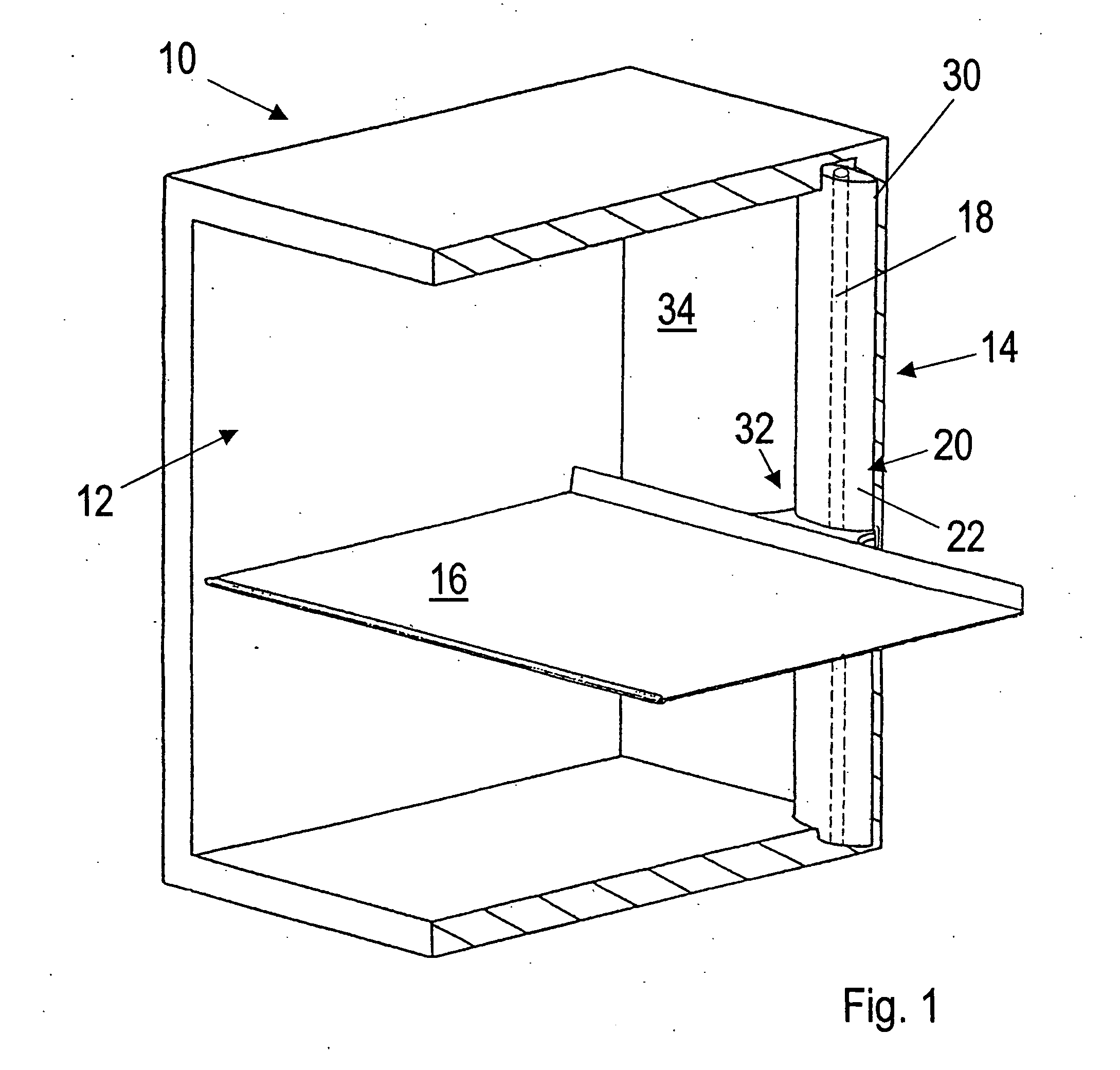
[0021] In a schematic, perspective view and in partial section, FIG. 1 shows a refrigerator 10 having an interior 12 in which a bracket 14 is arranged for receiving support shelves 16. The bracket 14 has a profiled rail 30, which is mounted, extending substantially vertically in the interior 12 of the household appliance 10, on the rear wall 34 of the household appliance 10 located opposite the door opening. Alternatively, it is possible to provide a plurality of vertically extending profiled rails arranged on different lateral walls in the interior of the refrigerator.

[0022] A support element 32 for holding the support shelf 16 is arranged on the profiled rail 30. The support element 32 can be displaced along the profiled rail 30 and can be fixed in place on the profiled rail 30 at a desired height by releasable fastening means which are not shown in the drawings.

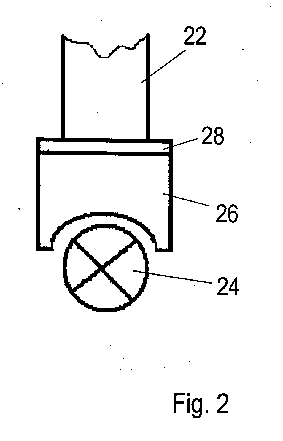
[0023] The profiled rail 30 has a transparent hollow body which is made, for example, of a plastic material reinforced b...


PUM


Abstract

A lighting installation for household appliances having an interior in which a bracket for receiving support shelves is arranged. The lighting arrangement includes an illuminating device integrated into at least a partial area of the bracket or entirely into the bracket. The illuminating device can include a fluorescent tube or an arrangement of a plurality of light-emitting diodes. Alternatively, at least a partial area of the bracket can be embodied as an optical waveguide, into which the light from a light source not arranged in the interior can be introduced.

Description

[0001] 1. Field of the Invention[0002] This invention relates to a lighting installation for household appliances, in which interior a bracket for receiving support shelves is arranged.[0003] 2. Discussion of Related Art[0004] The prior art teaches attaching a light to a lateral wall of an interior for lighting the interior of refrigerators. This light is switched on by a contact when the refrigerator door is opened. The arrangement of a light on a lateral wall has one disadvantage in that large containers for foods to be refrigerated or food packages cover the light. This results in a noticeable reduction of light output because a large portion of the refrigerator interior is shaded by foods to be refrigerated. Because known lights are customarily embodied as incandescent bulbs, it is also disadvantageous in that the heat generated by the incandescent bulbs unnecessarily heats the cooling chamber.[0005] From German Patent Reference DE 102 16 769.9, a bracket for support shelves in ...

Claims


Application Information

Patent Timeline
IPC IPC(8): F21V9/08F21V33/00F21W131/305F21Y101/02F21Y103/00F25D25/02F25D27/00H01L33/00H01L33/50
CPCF21V33/0044F21Y2101/02F25D25/02F25D27/00F25D2325/022F21W2131/305F21Y2115/10
Inventor HUBERT, STEFANHENKEL, WERNER
Owner SCHOTT AG
Learn More