Projectile for radially deploying sub-projectiles

Inactive Publication Date: 2004-12-09
METAL STORM LTD
View PDF18 Cites 17 Cited by
  • Summary
  • Abstract
  • Description
  • Claims
  • Application Information

AI Technical Summary

Benefits of technology

[0010] It is a further object of certain embodiments of the invention to provide a defence system that has improved control over deployment of projectiles and does not render the defended area unsafe for later civilian use.
[0068] The projectile of the present invention may deploy the sub-projectiles in a predetermined pattern that may be selected for particular applications. For example, in order to intercept and destroy an incoming missile, it is desirable to deploy the sub-projectiles in a manner that maximises the likelihood of the missile impacting with one or more of the sub-projectiles. Fragmentation systems have been employed to scatter fragments of a projectile in the path of an incoming missile. However, systems such as this that explode the projectile generally produce a band of fragments that disperse and form an expanding spherical shell. The projectiles may deploy the sub-projectiles of the invention in a more homogeneous manner throughout the space occupied by the predetermined pattern. By controlling the timing of the firing of the sub-projectiles it is possible to establish a three dimensional "frag" pattern having a substantially homogeneous distribution of sub-projectiles. Alternatively, the sub-projectiles may be concentrated in areas where the missile is more likely to be intercepted so as to increase the effectiveness of the deployed sub-projectiles.

Problems solved by technology

However, such fragmenting projectiles produce a relatively thin, shell like fragment casing pattern.

Method used


Image

  • Projectile for radially deploying sub-projectiles
  • Projectile for radially deploying sub-projectiles
  • Projectile for radially deploying sub-projectiles

Examples


Embodiment Construction

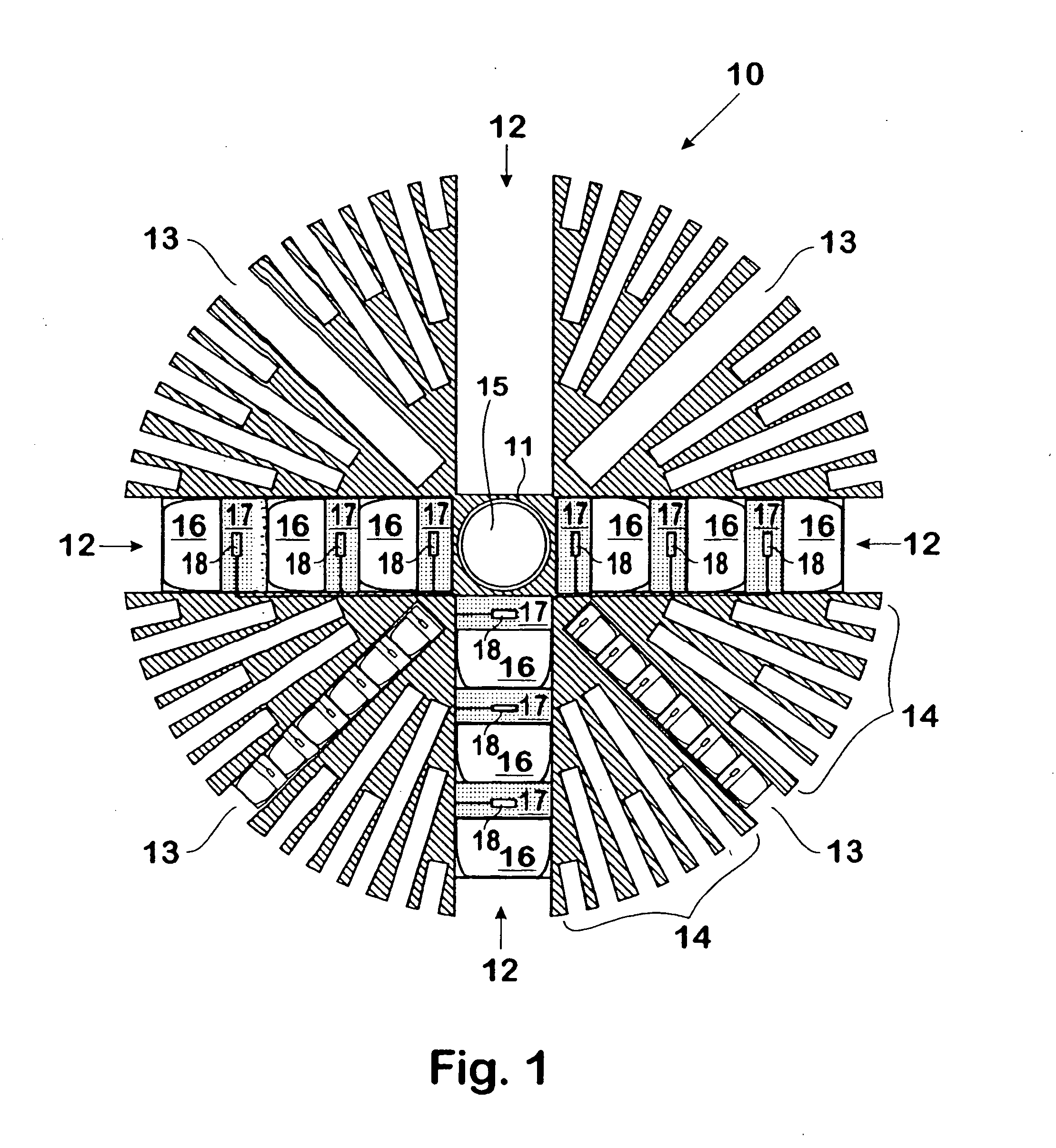
[0082] FIG. 1 shows a projectile 10 having six (6) large bore barrels 12 of a convenient calibre, although only four (4) are shown in this cross sectional representation. The remaining two (2) large bore barrels (extending perpendicularly to the page) are depicted at 11. The cross sectional representation also shows four (4) medium bore barrels 13 of medium calibre, and forty-eight (48) small bore barrels 14 of relatively small calibre. The large bore 12, medium bore 13 and small bore 14 barrels each contain a plurality of axially disposed sub-projectiles 16, as represented on the drawing. The sub-projectiles are associated with propellant charges 17 and ignition means 18, which ignition means may be sequentially fired under the control of an electronic controller 15. In some embodiments, the projectile 10 may also contain an explosive charge for terminal detonation.

[0083] The electronic controller 15, which is disposed in the centre of the projectile 10 behind the barrels 11, 12 in...


PUM


Abstract

A projectile (10) for firing from a barrel, said projectile including a multiplicity of barrel assemblies (12, 13, 14) radially disposed from the centre of mass of the projectile, wherein each of said multiplicity of barrel assemblies includes a plurality of sub-projectiles (16) axially disposed within a barrel; each of said sub-projectiles associated with a discrete propellent charge (17) for propelling a respective sub-projectile from the barrel, wherein said projectile is capable of selectively firing sub-projectiles (16), suitably with the aid of primers (18) each coupled to an electronic controller (15). to provide a predetermined pattern of deployed sub-projectiles. A defence system employing projectiles of the type described is also disclosed, together with a method for disguising the launch location of a projectile utilising divert propulsion.

Description

[0001] 1. Field of the Invention[0002] This present invention relates to the deployment of objects in the nature of projectiles and in particular, although not exclusively, to the formation of a predetermined pattern of deployed sub-projectiles by a parent projectile and to a projectile launching method for masking the launch location of a projectile.[0003] 2. Discussion of the Background Art[0004] Projectiles that incorporate explosive charges have been used as fragmentation devices to deploy a plurality of fragments. In a simple form the casing of such a projectile fragments on detonation of the explosive charge such that individual fragments of the casing are deployed radially to form a fragmentation pattern roughly in the shape of the surface of a sphere.[0005] In other configurations, the shape of the charge and the configuration of the casing may be varied to control the fragmentation pattern. However, such fragmenting projectiles produce a relatively thin, shell like fragment...

Claims


Application Information

Patent Timeline
IPC IPC(8): F41A19/58F41F1/00F41A19/68F41H11/02F42B12/48F42B12/60F42B12/70
CPCF41A19/58F41A19/68F41H11/02F42B12/60F42B12/70
Inventor O'DWYER, JAMES MICHAELO'DWYER, SEAN MICHAEL
Owner METAL STORM LTD
Why Eureka
Try Eureka