
Commutator for electric motors

a technology for electric motors and commutators, which is applied in the manufacture of slip rings, current collectors, dynamo-electric components, etc., can solve the problems of relatively high engineering effort and expense, reduced service life of electric motors, and difficulty in achieving the effect of reducing the cost of electric commutators

Inactive Publication Date: 2004-12-02
ROBERT BOSCH GMBH
View PDF10 Cites 2 Cited by
  • Summary
  • Abstract
  • Description
  • Claims
  • Application Information

AI Technical Summary

Benefits of technology

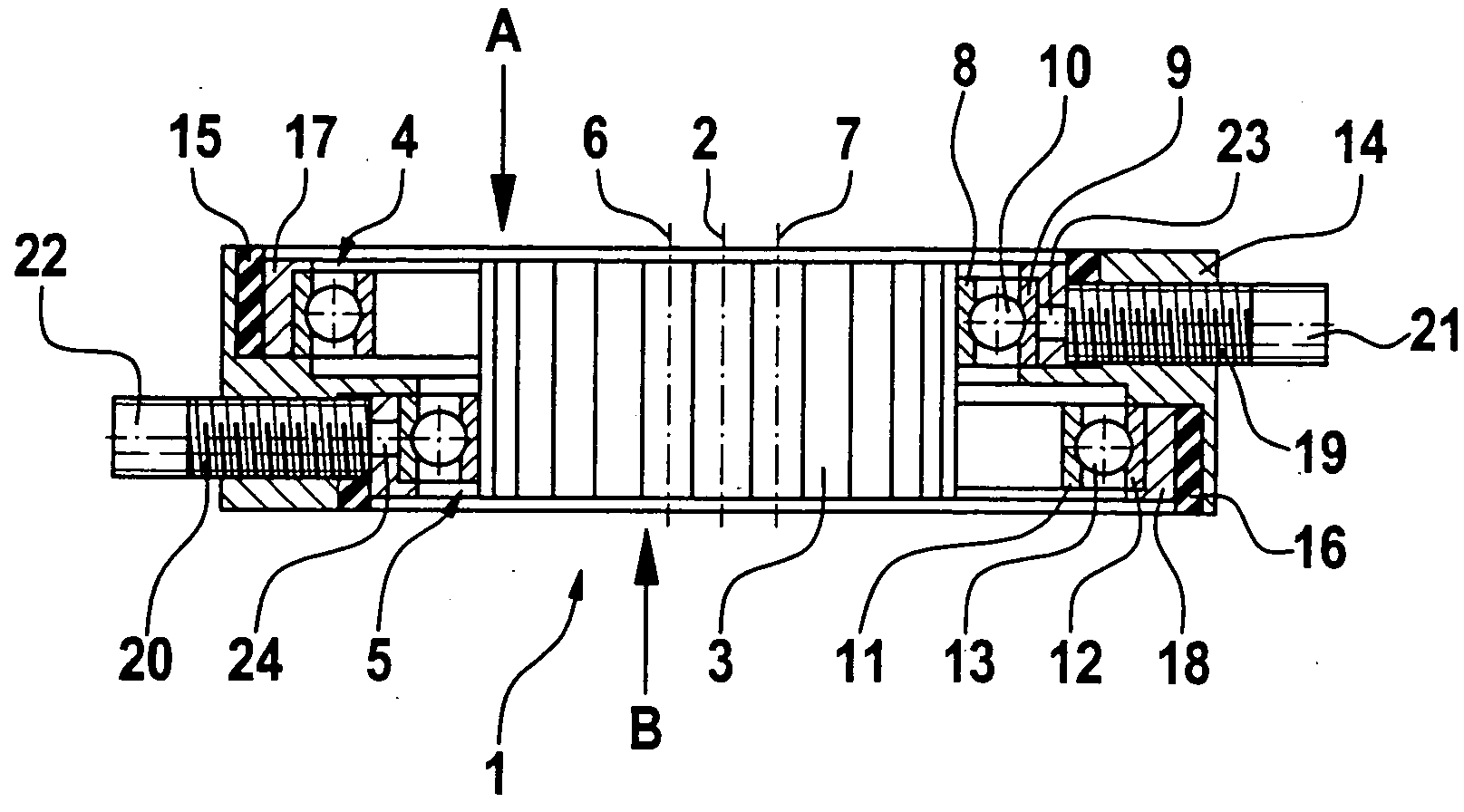
[0004] The aforementioned object is attained with the characteristics of claim 1. The collector of the motor has electrical-contact means which during one rotation of the collector each touch at least two of a plurality of commutator laminations present on the collector and thus establish an electrical connection between the applicable commutator laminations and external current connections. According to the invention, the electrical-contact means comprise at least two electrically conductive cylinders, disposed in line with one another in the axial direction of the collector, whose longitudinal axes are parallel to the longitudinal axis of the collector. The at least two cylinders are placed in such a way relative to the collector and have a diameter such that the collector in its rotation rolls over the inside faces or outside faces of the at least two cylinders, and in the process each of the cylinders present is only ever touched by one lamination of the collector. Because the collector rolls with its laminations on the cylinders, and there is no sliding contact between the two, the parts belonging to the commutator are subject to only extremely slight wear. In a motor equipped with such a commutator, no replacement of parts, as is the case with a commutator that has carbon brushes, is necessary over the entire service life of the commutator. Moreover, in the mechanical commutator of the invention, the likelihood of failure is even less than in an electrically commutated motor, since electrical components of the commutation circuit are subject to a certain likelihood of failure.
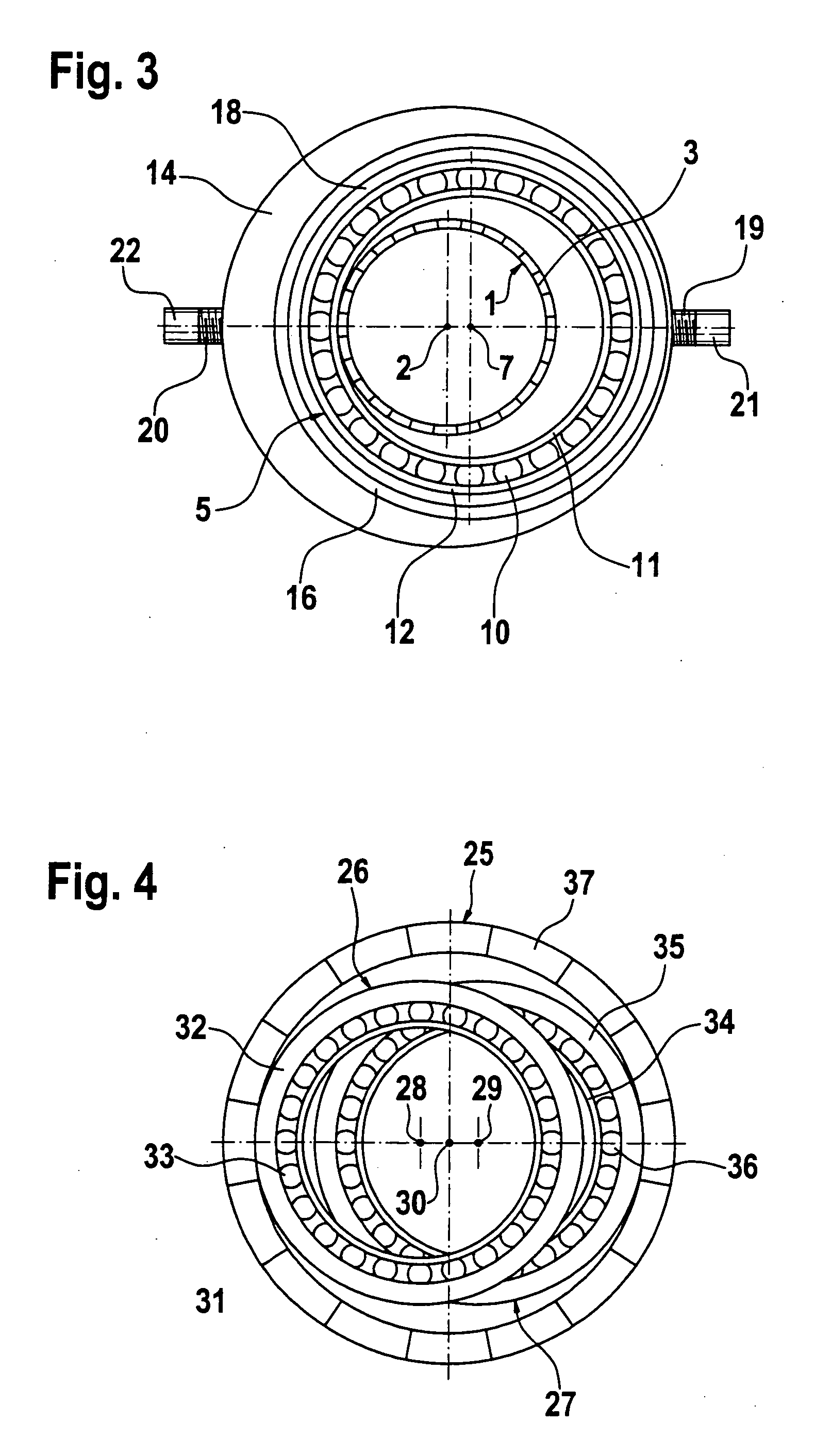
[0011] The invention is described in further detail below in terms of several exemplary embodiments shown in the drawing. Shown are:
[0006] One advantageous embodiment of the electrically conductive cylinders provides that they are eccentrically supported relative to the longitudinal axis of the collector.

Problems solved by technology

Such commutators have the disadvantage of being highly vulnerable to wear, so that the service life of an electric motor is reduced considerably unless the carbon brushes are replaced.
The replaceability of the carbon brushes necessitates relatively high engineering effort and expense.
The electronic circuits required for the electric commutation are relatively complicated and thus cost-intensive.

Method used


Image

  • Commutator for electric motors
  • Commutator for electric motors
  • Commutator for electric motors

Examples


Embodiment Construction

[0016] FIG. 1 shows a longitudinal section through a commutator of an electric motor, which for example is a direct-current motor or a universal motor. The commutator has a collector 1, which is supported rotatably about a longitudinal axis 2; this longitudinal axis coincides with the axis of rotation of the rotor, not shown in the drawing and receiving a plurality of armature windings, of the electric motor. The collector 1 has a plurality of laminations 3 on its outer circumference in a known manner, and these laminations are electrically connected to the armature windings and by way of which a current is delivered to the armature windings. The means with which one or more laminations 3 of the collector 1 are supplied with a current and with which the current is drawn again from one or more other laminations 3 of the collector 1 are described hereinafter. These contact means that deliver and draw current can be seen from the cross section through the commutator shown in FIG. 1; th...


PUM

PropertyMeasurementUnit
electrically conductiveaaaaaaaaaa
diameteraaaaaaaaaa
currentaaaaaaaaaa

Abstract

The commutator has a cylindrical collector (1), disposed on a motor armature shaft, and electrical-contact means (4, 5), which during one rotation of the collector (1) touch at least two each of a plurality of commutator laminations (3) that are present on the collector (1) and thereby establish an electrical connection between the applicable commutator laminations and external current connections (21, 22). The electrical-contact means becomes especially low-wearing because the electrical-contact means comprise at least two electrically conductive cylinders (4, 5) disposed in line with one another in the axial direction of the collector (1), the longitudinal axes (6, 7) are parallel to the longitudinal axis (2) of the collector (1); and that the at least two cylinders (4, 5) are placed relative to the collector (1) in such a manner and have a diameter such that the collector (1), in its rotation, rolls over the inside faces (8) or the outside faces of the at least two cylinders (4, 5), and in the process each of the cylinders (4, 5) is touched always by only one lamination (3) of the collector (3).

Description

Prior Art[0001] The present invention relates to a commutator for electric motors, which has a cylindrical collector disposed on a motor armature shaft and has electrical-contact means, which during one rotation of the collector touch at least two each of a plurality of commutator laminations that are present on the collector and thus establish an electrical connection between the applicable commutator laminations.[0002] One such commutator, in which carbon brushes slide on the laminations of the collector and thus transmit a direct current into the armature windings, is known for instance from German Patent Disclosure DE 197 52 626 A1. Such commutators equipped with carbon brushes are typically used for direct-current motors or universal motors. Such commutators have the disadvantage of being highly vulnerable to wear, so that the service life of an electric motor is reduced considerably unless the carbon brushes are replaced. The replaceability of the carbon brushes necessitates r...

Claims


Application Information

Patent Timeline
Patent Type & Authority Applications(United States)
IPC IPC(8): H01R39/28H01R39/64H02K13/00
CPCH01R39/28Y10T29/49011H01R39/643
Inventor HABELE, MICHAEL
Owner ROBERT BOSCH GMBH
Learn More