
Pulsed solar simulator with improved homogeneity

Active Publication Date: 2004-11-11
AIRBUS DEFENCE & SPACE
View PDF4 Cites 5 Cited by
  • Summary
  • Abstract
  • Description
  • Claims
  • Application Information

AI Technical Summary

Benefits of technology

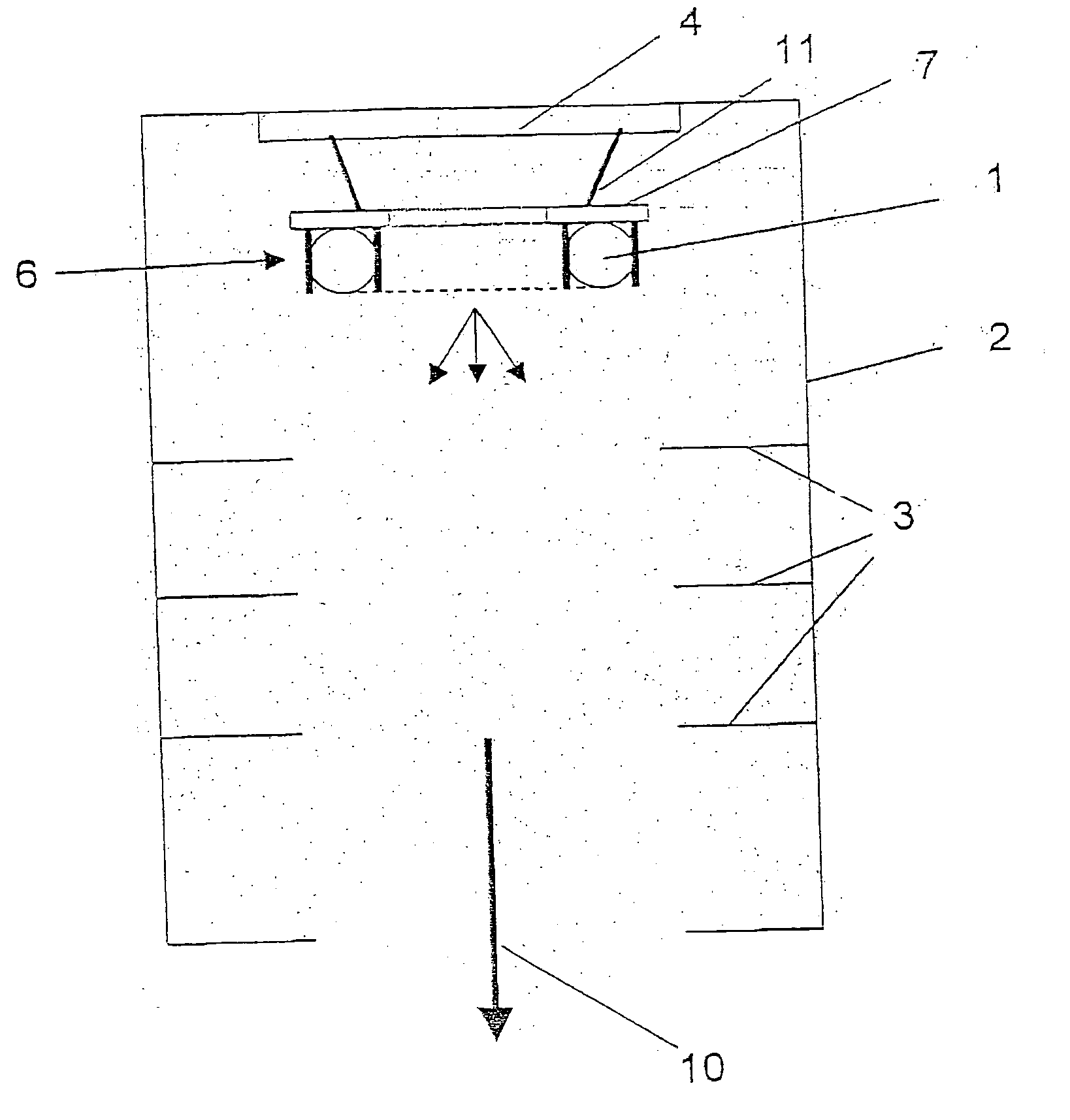
[0013] If now, as in the case of the present invention, the mirror element is embodied or formed at least in part of metal, a voltage can be applied to the mirror element. In particular, a substructure group or a constructional sub-element of the mirror element, such as, e.g., a frame, a holder or the mirror surface can be embodied or formed entirely or in part of metal. The applied voltage supports the pulsed ignition of the radiation source and thereby helps to make a homogenous ignition of the radiation source. In this regard, gas-filled tubes are generally used as radiation sources, and an ignition voltage is applied to these tubes via suitably arranged electrodes. Alternatively to an ignition voltage used specially for the ignition or in addition to this ignition voltage, a constant voltage can be applied to the ends of the gas-filled tubes. With such radiation sources, upon ignition, a luminous discharge is transmitted from one electrode through the tube to the other electrode, which leads to an inhomogeneous radiation effect. The application of an additional voltage to the mirror element directly adjacent to the radiation source leads to a much quicker and more homogenous ignition of the radiation source. Thus, according to the invention, the mirror element is positioned adjacent the radiation source, and preferably is positioned to directly abut against the radiation source in order to achieve the best possible effect upon ignition and, thus, the best possible homogeneity.
[0014] In addition, the mirror element reflects radiation components of the radiation source that are irradiated against the desired irradiation direction of the solar simulator. Thus, the level of effectiveness of the radiation source is increased, whereby overall less energy is required. Moreover, the radiation source can be operated with lower power with the result that the maximum of the irradiation spectrum shifts into the infrared range. This is a desirable and advantageous effect, since, particularly in the infrared range, conventional solar simulators exhibit a radiation intensity that is too low compared to the solar spectrum. The homogeneity of the irradiation is also advantageously improved through the reflection effect of the mirror elements in the direction of the irradiation direction of the solar simulator.
[0017] It has been shown that metals such as gold as well as metals with oxide layers, such as in particular light metals and also semiconductors with oxide layers, feature very good reflection properties particularly in the infrared range. These materials in particular can therefore be used within the scope of the current invention in an advantageous manner.
[0019] The homogeneity of the irradiation can be increased even further in that the radiation source is surrounded by a housing that features several screen elements arranged one behind the other in the wall area in the irradiation direction. These screen elements intercept those radiation components of the radiation source that are not irradiated directly or chiefly in the direction of the irradiation direction. In addition, these screen elements can preferably be covered with a low-reflection coating or can be made of a low-reflection material in order to largely eliminate scattered radiation.
[0020] A preferred further development of the invention provides that the radiation source and / or the mirror element is connected to a carrier plate of granite via holders. The surface of the carrier plate is thereby either smoothly polished or microscopically roughened in order to have a reduced reflection effect. Such a granite plate has proven to be an ideal carrier plate which has a high stability, in particular also a high temperature stability, as well as also the necessary stability and insulation effect with respect to the high voltages applied via the holders and conducting feeds to the radiation source and / or the at least one mirror element.

Problems solved by technology

However, pulsed radiation sources are not used as radiation sources here.
However, none of these possibilities from the prior art gives an indication of how to achieve an improved homogeneity of the irradiation of the target to be irradiated.

Method used


Image

  • Pulsed solar simulator with improved homogeneity
  • Pulsed solar simulator with improved homogeneity
  • Pulsed solar simulator with improved homogeneity

Examples


Embodiment Construction

[0046] The particulars shown herein are by way of example and for purposes of illustrative discussion of the embodiments of the present invention only and are presented in the cause of providing what is believed to be the most useful and readily understood description of the principles and conceptual aspects of the present invention. In this regard, no attempt is made to show structural details of the present invention in more detail than is necessary for the fundamental understanding of the present invention, the description taken with the drawings making apparent to those skilled in the art how the several forms of the present invention may be embodied in practice.

[0047] FIG. 1 shows a radiation source 1 with a mirror element 7 in the paper plane merely to simplify the representation. In fact, radiation source 1 and mirror element 7 are arranged in a plane perpendicular to the irradiation direction 10 of the solar simulator, i.e., perpendicular to the page, so that the mirror refl...


PUM

PropertyMeasurementUnit
Electric potential / voltageaaaaaaaaaa
Reflectionaaaaaaaaaa

Abstract

Solar simulator that includes a pulsed radiation source for generating electromagnetic radiation, and at least one mirror element is arranged in a region of the radiation source. The at least one mirror element is structured and arranged to reflect components of radiation from the radiation source essentially in an intended irradiation direction. Further, the at least one mirror element, formed at least in part of metal, is positioned adjacent to the radiation source and is structured to receive at least a part of an ignition voltage of the pulsed radiation source. The instant abstract is neither intended to define the invention disclosed in this specification nor intended to limit the scope of the invention in any way.

Description

[0001] The present application claims priority-under 35 U.S.C. .sctn. 119 of German Patent Application No. 103 06 150.9, filed on Feb. 14, 2003, the disclosure of which is expressly incorporated by reference herein in its entirety.[0002] 1. Field of the Invention[0003] The present invention relates to a pulsed solar simulator, and, in particular, a solar simulator that can be used for measuring solar cells such as single-junction solar cells and multi-junction solar cells.[0004] 2. Discussion of Background Information[0005] Solar simulators are used to simulate natural sunlight to make it possible to study the effects of sunlight on certain objects to be irradiated, even under laboratory conditions. A special application is the study of the capacity of solar cells.[0006] Solar simulators are known, e.g., from U.S. Pat. No. 4,641,227, in which simulation of sunlight is realized through a suitable arrangement and filtering of two independent radiation sources and a subsequent overlapp...

Claims


Application Information

Patent Timeline
IPC IPC(8): F21S8/00F21V7/22F21V14/08
CPCF21S8/006F21V7/22F21V14/08F21Y2103/02F21Y2103/30F21V7/24F21V7/28
Inventor AHRENS, KLAUS-ARMINHAMPE, CARSTENPREITNACHER, HEINRICH
Owner AIRBUS DEFENCE & SPACE
Learn More