Adjustable telescope tracking platform

a telescope and tracking platform technology, applied in the direction of direction/deviation determining electromagnetic systems, direction finders using radio waves, instruments, etc., can solve the problems of inability to automate tracking ability, large conventional mounting system, low cost of this type of telescope, etc., to achieve accurate tracking of celestial objects, easy adjustment, and high accuracy

Inactive Publication Date: 2004-11-04
JOHNSONIAN DESIGNS
View PDF5 Cites 0 Cited by
  • Summary
  • Abstract
  • Description
  • Claims
  • Application Information

AI Technical Summary

Benefits of technology

[0007] The present invention provides for an easily adjustable motorized equatorial tracking platform onto which can be mounted a telescope or other instrument which can compensate for the rotational movement of the earth, and allow the instrument to track a celestial object with high accuracy at any desired latitude setting. The general design comprises two rolling surfaces, each in contact with a pair of rollers which each have an adjustment for the latitude setting. One rolling surface is a complex 3-dimensional contour, which provides for a differing radius for each latitude setting, while the other rolling surface is of fixed radius, but with adjustable latitude angle. By varying the angle of the roller pairs, the virtual axis of rotation is changed to be aligned parallel to the earth's rotational axis. When one or more of the rollers are motorized, and the virtual rotational axis of the platform is aligned with the earth's rotational axis, the invention will allow a telescope to accurately track a celestial object. By positioning the telescope on the top table surface so that the telescope center of gravity aligns with the virtual rotational axis, rotational moments are minimized and very small motors can be used to drive the telescope.
[0009] The platform consists of an adjustable front truncated bearing plate surface, of sufficient radius to ensure that the virtual polar axis which passes thru it's center of curvature is located at a higher elevation than the center of gravity of the telescope placed upon it. This front bearing surface segment is cylindrical, of fixed thickness, and rides in two grooved drive rollers spaced sufficiently apart to provide lateral support stability. One or both rollers can be motorized so as to impart a rotational translation to the front bearing plate solely by friction. The front bearing plate is attached to a somewhat horizontal top platform surface by means of an adjustable hinge assembly, which can be clamped at a user defined acute angle. The motor and drive roller assembly is carried on a motor / roller carrying plate, and is likewise adjustably hinged and clamped to a bottom horizontal base surface. This surface resides on the ground. A rear 3-dimensionally contoured bearing is spaced some defined distance from the front truncated bearing plate, and securely fastened to the underside of the top platform surface. This contoured bearing surface has machined into it a plurality of differing radii which are a function of the contact angle of a single or pair of rear support rollers, this contact angle being set by a hinged rear roller mounting bracket mounted to the bottom horizontal base surface. For northern hemisphere installations, the front bearing surface faces north. For southern hemisphere installations, it faces south, and the drive roller rotation is reversed. In both cases, all hinge angles are adjusted to align the virtual rotational axis of the platform with the earth's rotational axis. By fine adjustments of the azimuth base position and altitude virtual axis alignment to the celestial pole, and motor speed rate, very precise tracking is possible, which will allow long exposure imaging or photography to be performed.

Problems solved by technology

As telescopes become larger, conventional mounting systems become large, heavy, and unwieldy.
These are incapable of automated tracking ability, unless each axis is fitted with complex motors and drive electronics.
This is inconsistent with the low cost of this type of telescope.
Thus, these platforms are unable to be mass produced and inventoried for low cost, and should the user ever move or desire to use the platform at a different latitude, another complete table must be purchased, often with long lead times.
Accordingly, these prior approaches have failed to meet the need of the telescope user.

Method used


Image

  • Adjustable telescope tracking platform
  • Adjustable telescope tracking platform
  • Adjustable telescope tracking platform

Examples


Embodiment Construction

[0018] The drawing describes the preferred embodiment of the present invention. While the configurations according to the illustrated embodiment are preferred, it is envisioned that alternate configurations of the present invention may be adopted without deviating from the invention as portrayed. The preferred embodiment is discussed hereafter.

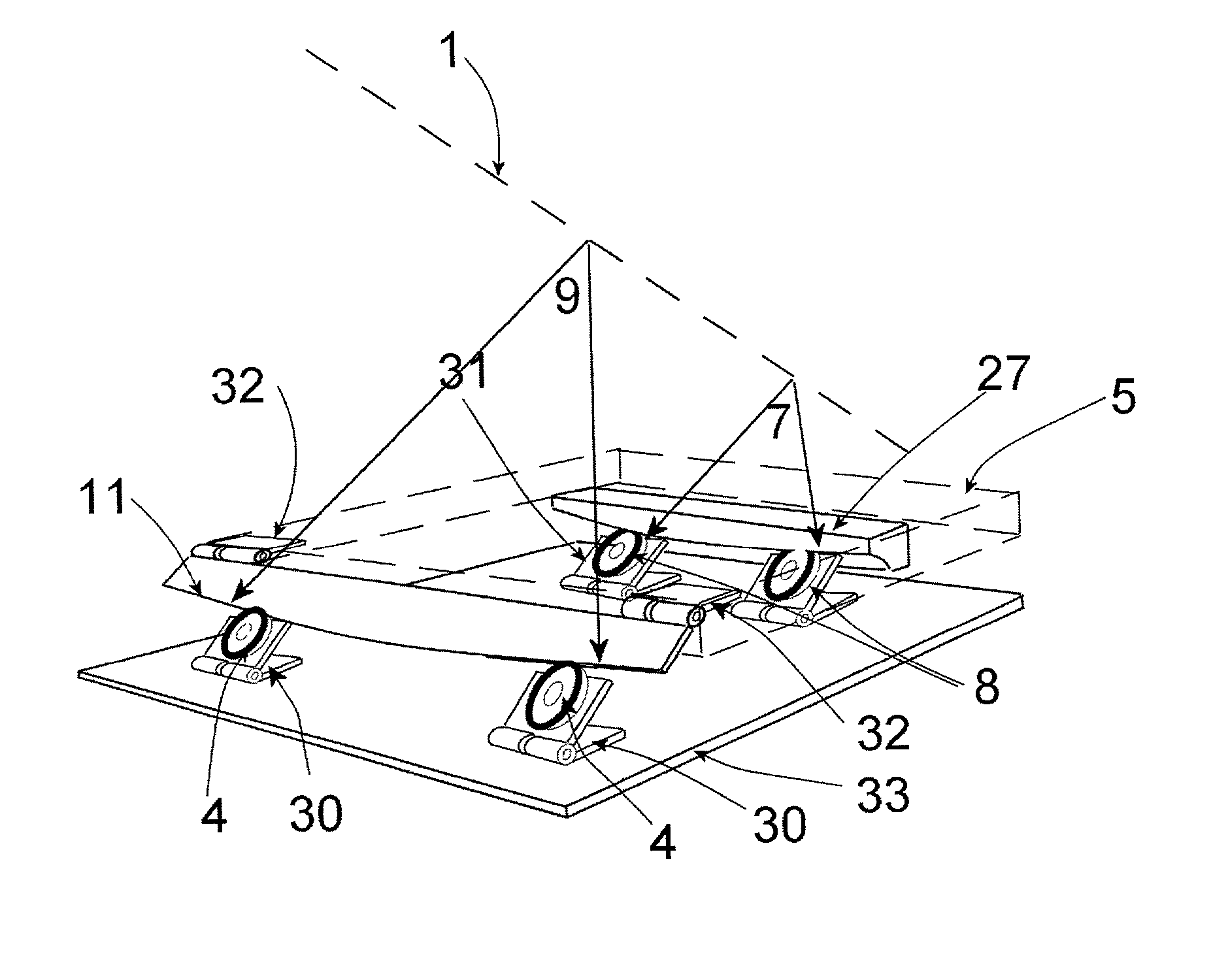
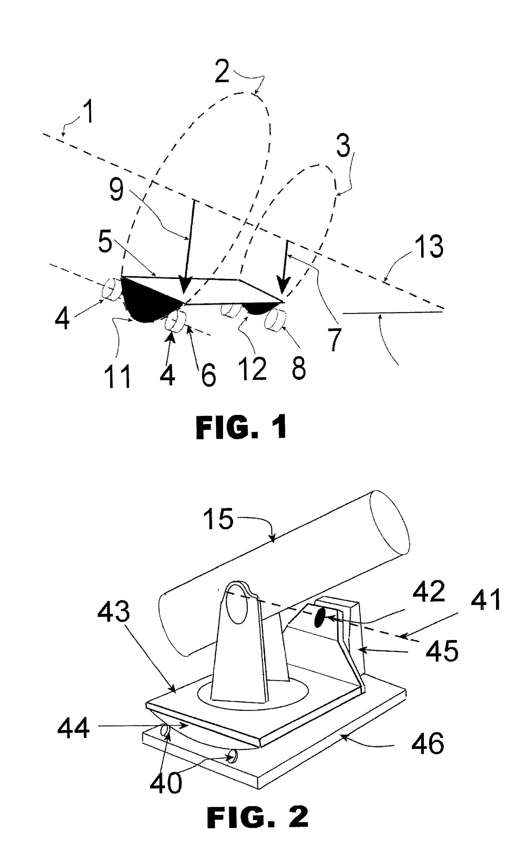
[0019] Referring to FIG. 1, the principles of how an equatorial type tracking platform operates is illustrated. In order for an instrument to track celestial objects, it is necessary to rotate the instrument counter to the earth's rotational axis. Such an axis exists as a virtual axis 1, with the rate of rotation of top platform 5 being equal and opposite to the earth's rotational rate. The creation of virtual axis 1 can be seen to be created by virtual bearing surfaces 2, and 3, which have their centers of curvature aligned with 1. Only a portion of such bearing surfaces needs physically to exist. These real surfaces are the front bearing sur...


PUM


Abstract

An equatorial tracking platform for a telescope that comprises two rolling surfaces, each in contact with a pair of rollers which each have an adjustment for the latitude setting. One rolling surface is a complex 3-dimensional contour, which provides for a differing radius for each latitude setting, while the other rolling surface is of fixed radius. By varying the angle of the roller pairs, the virtual axis of rotation is changed to be aligned parallel to the earth's rotational axis, thus allowing a telescope to accurately track a celestial object.

Description

[0001] I. Field of the Invention[0002] The present invention relates optical and radio telescope and satellite tracking devices which must compensate for the rotational movement of the earth in order to accurately track a celestial object.[0003] II. Description of the Relevant Art[0004] As telescopes become larger, conventional mounting systems become large, heavy, and unwieldy. Popular today are large alt-azimuth mounted telescopes of a type referred to as Dobsionan. These are incapable of automated tracking ability, unless each axis is fitted with complex motors and drive electronics. This is inconsistent with the low cost of this type of telescope. Thus, these telescopes must be moved by hand in order to tack or follow an object.[0005] In order to allow the Dobsionan telescope to track, low profile equatorial tracking tales were developed and popularized. These consist of two horizontal table like surfaces which create a virtual axis of revolution aligned with the earth's rotatio...

Claims


Application Information

Patent Timeline
Patent Type & Authority Applications(United States)
IPC IPC(8): G01S3/04G01S3/781G01S3/786G02B23/00H01Q1/12H01Q3/02
CPCG01S3/04G01S3/781G01S3/7867H01Q1/125H01Q3/02
Inventor JOHNSON, SAMUEL ALAN
Owner JOHNSONIAN DESIGNS
Why Eureka
Try Eureka