
Mechanism for FRU fault isolation in distributed nodal environment

a nodal environment and fault isolation technology, applied in the field of computer systems, can solve problems such as inability to determine the original source of the primary, many errors are allowed to propagate, and in-line error correction can introduce a significant delay into the system,

Inactive Publication Date: 2004-10-28
IBM CORP
View PDF7 Cites 30 Cited by
  • Summary
  • Abstract
  • Description
  • Claims
  • Application Information

AI Technical Summary

Problems solved by technology

While some errors can be corrected by error correction code (ECC) logic embedded in these components, there is still a need to determine the cause of these errors since the correction codes are limited in the number of errors they can both correct and detect.
When the system has an fault or defect that causes a system error, it can be difficult to determine the original source of the primary error since the corruption can cause secondary errors to occur downstream on other chips or devices connected to the SMP fabric.
Many errors are allowed to propagate due to performance issues.
In-line error correction can introduce a significant delay into the system, so ECC might be used only at the final destination of a data packet (the data "consumer") rather than at its source or at an intermediate node.
Accordingly, for a recoverable error, there often lacks sufficient time to ECC correct before forwarding the data without adding undesirable latency to the system, so bad data may intentionally be propagated to subsequent nodes or chips.
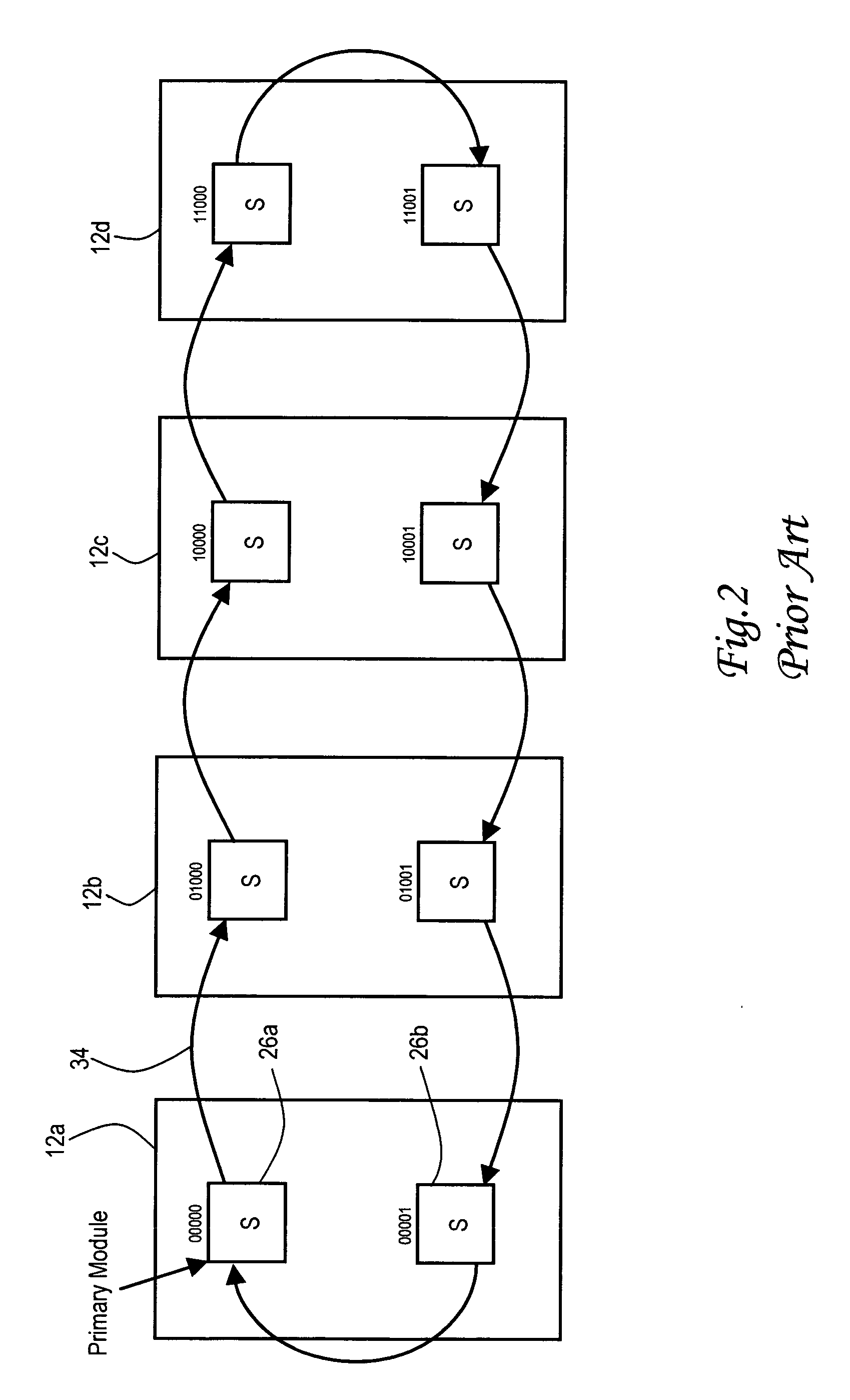
While this approach to fault isolation is feasible with a simple ring (single-loop) topology, it is not viable for more complicated processing unit constructions which might have, for example, multiple loops criss-crossing in the communications topology.
In such constructions, there is no guarantee that the counter with the largest count corresponds to the defective component, since the error may propagate through the topology in an unpredictable fashion determined by exactly which chip experiences the primary error and how the particular data or command packet is being routed along the fabric topology.
Although a fault isolation system might be devised having a central control point which could monitor the components to make the determination, the trend in modern computing is moving away from such centralized control since it presents a single failure point that can cause a system-wide shutdown.
When an error is reported, diagnostics code logs an error event for the particular computer component associated with the counter containing the lowest count value.

Method used


Image

  • Mechanism for FRU fault isolation in distributed nodal environment
  • Mechanism for FRU fault isolation in distributed nodal environment
  • Mechanism for FRU fault isolation in distributed nodal environment

Examples


Embodiment Construction

)

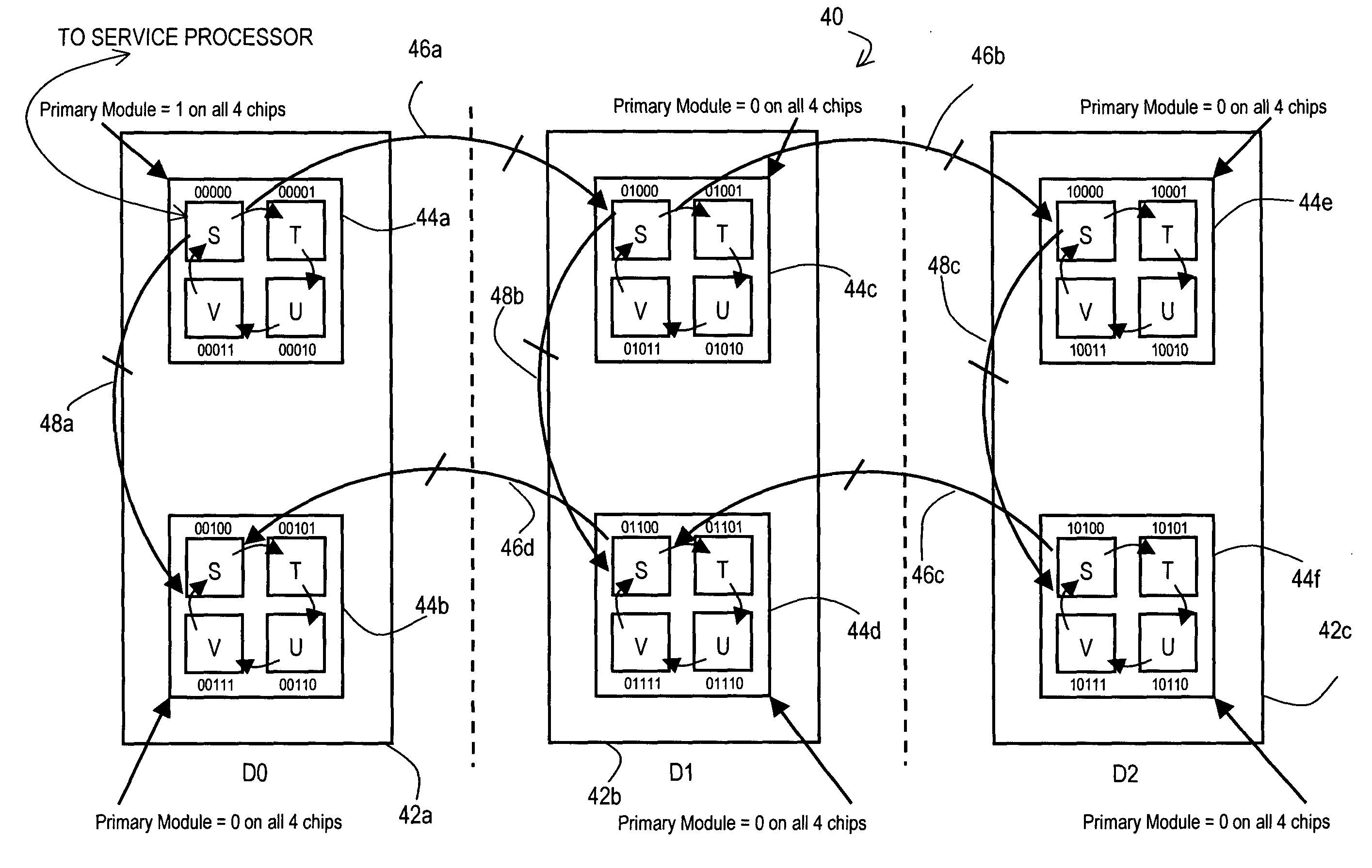
[0024] With reference now to the figures, and in particular with reference to FIG. 3, there is depicted one implementation of a processor group 40 for a symmetric multi-processor (SMP) computer system constructed in accordance with the present invention. In this particular implementation, processor group 40 is composed of three drawers 42a, 42b and 42c of processing units. Although only three drawers are shown, the processor group could have fewer or additional drawers. The drawers are mechanically designed to slide into an associated frame for physical installation in the SMP system. Each of the processing unit drawers includes two multi-chip modules (MCMs), i.e., drawer 42a has MCMs 44a and 44b, drawer 42b has MCMs 44c and 44d, and drawer 42c has MCMs 44e and 44f. Again, the construction could include more than two MCMs per drawers. Each MCM in turn has four integrated chips, or individual processing units (more or less than four could be provided). The four processing units for ...


PUM


Abstract

A method of identifying a primary source of an error which propagates through a computer system and generates secondary errors, by initializing a plurality of counters that are respectively associated with the computer components (e.g., processing units), incrementing the counters as the computer components operate but suspending a given counter when its associated computer component detects an error, and then determining which of the counters contains a lowest count value. The counters are synchronized based on relative delays in receiving an initialization signal. When an error is reported, diagnostics code logs an error event for the particular computer component associated with the counter containing the lowest count value.

Description

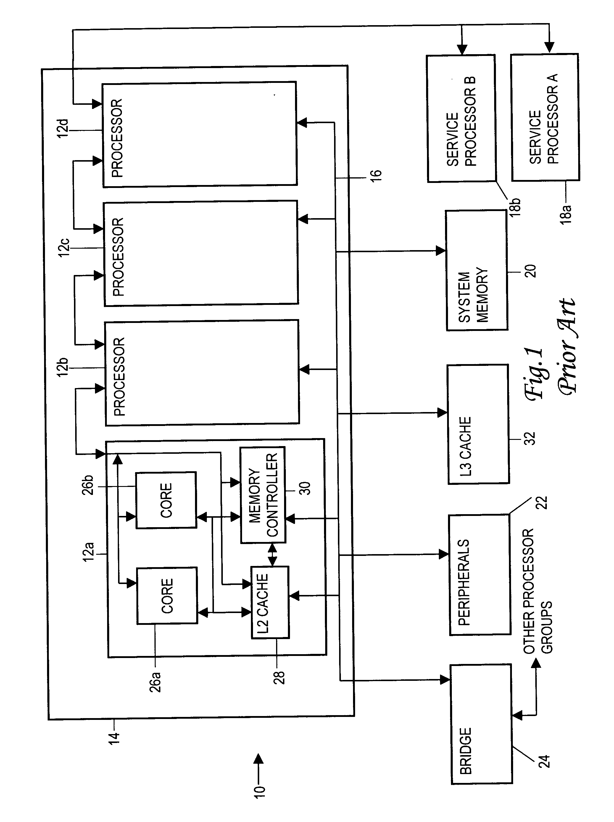
[0001] 1. Field of the Invention[0002] The present invention generally relates to computer systems, and more specifically to an improved method of determining the source of a system error which might have arisen from any one of a number of components, particularly field replaceable units such as processing units, memory devices, etc., which are interconnected in a complex communications topology.[0003] 2. Description of the Related Art[0004] The basic structure of a conventional symmetric multi-processor computer system 10 is shown in FIG. 1. Computer system 10 has one or more processing units arranged in one or more processor groups; in the depicted system, there are four processing units 12a, 12b, 12c and 12d in processor group 14. The processing units communicate with other components of system 10 via a system or fabric bus 16. Fabric bus 16 is connected to one or more service processors 18a, 18b, a system memory device 20, and various peripheral devices 22. A processor bridge 24...

Claims


Application Information

Patent Timeline
IPC IPC(8): G06F11/22G06F11/34G06F15/16H02H3/05
CPCG06F11/0727G06F11/079G06F11/0724G06F15/16
Inventor FLOYD, MICHAEL STEPHENLEITNER, LARRY SCOTTREICK, KEVIN FRANKLIN
Owner IBM CORP
Learn More