
System and method for milking animals

Inactive Publication Date: 2004-09-23
DELAVAL HLDG AB
View PDF11 Cites 13 Cited by
  • Summary
  • Abstract
  • Description
  • Claims
  • Application Information

AI Technical Summary

Benefits of technology

[0019] It is still a further object of the present invention to provide a computer-controlled method for milking of animals, which facilitates milking of at least two animals simultaneously.
[0020] It is yet a further object of the invention to provide such a method, which is simple, reliable, flexible, and of reasonably low cost.
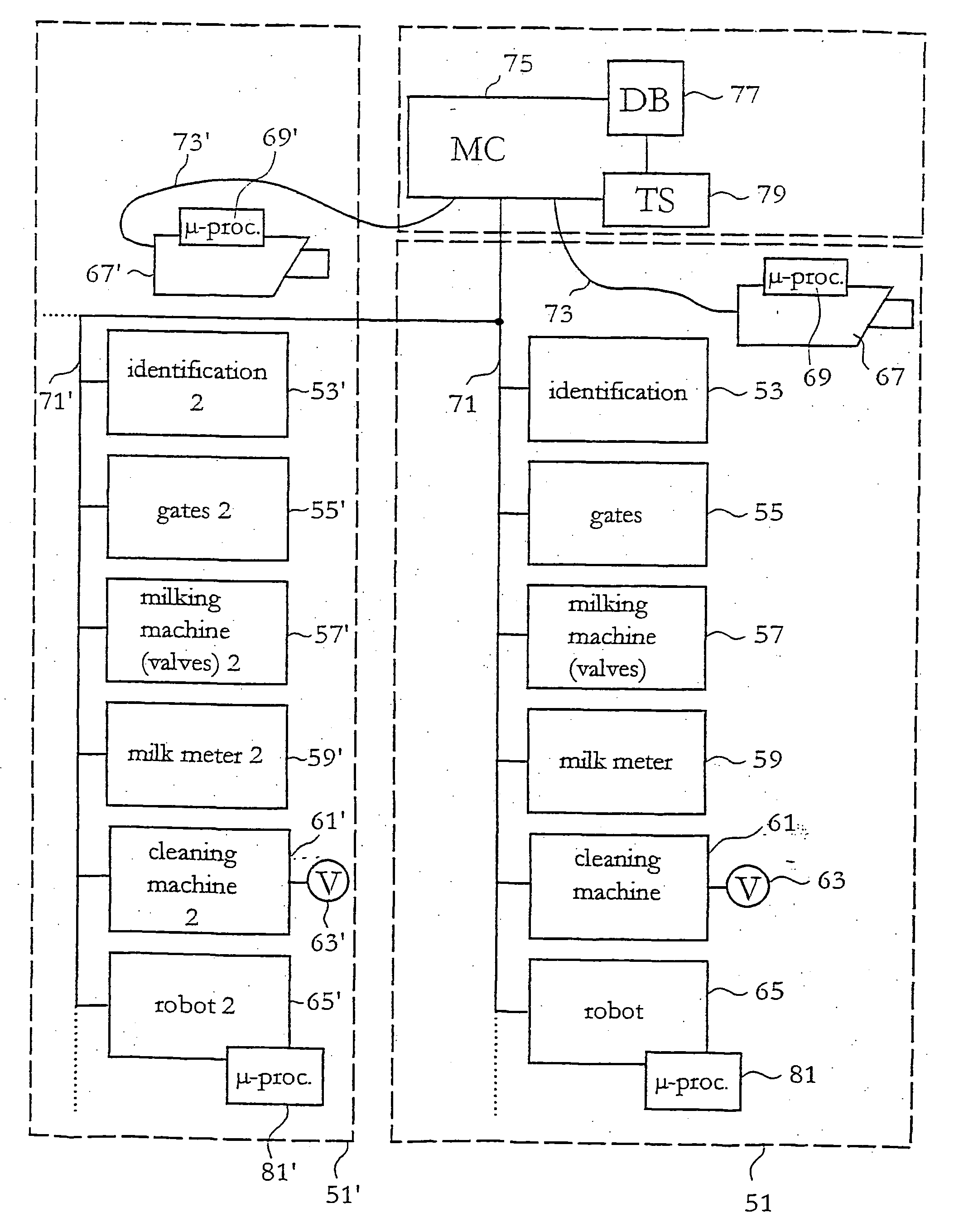
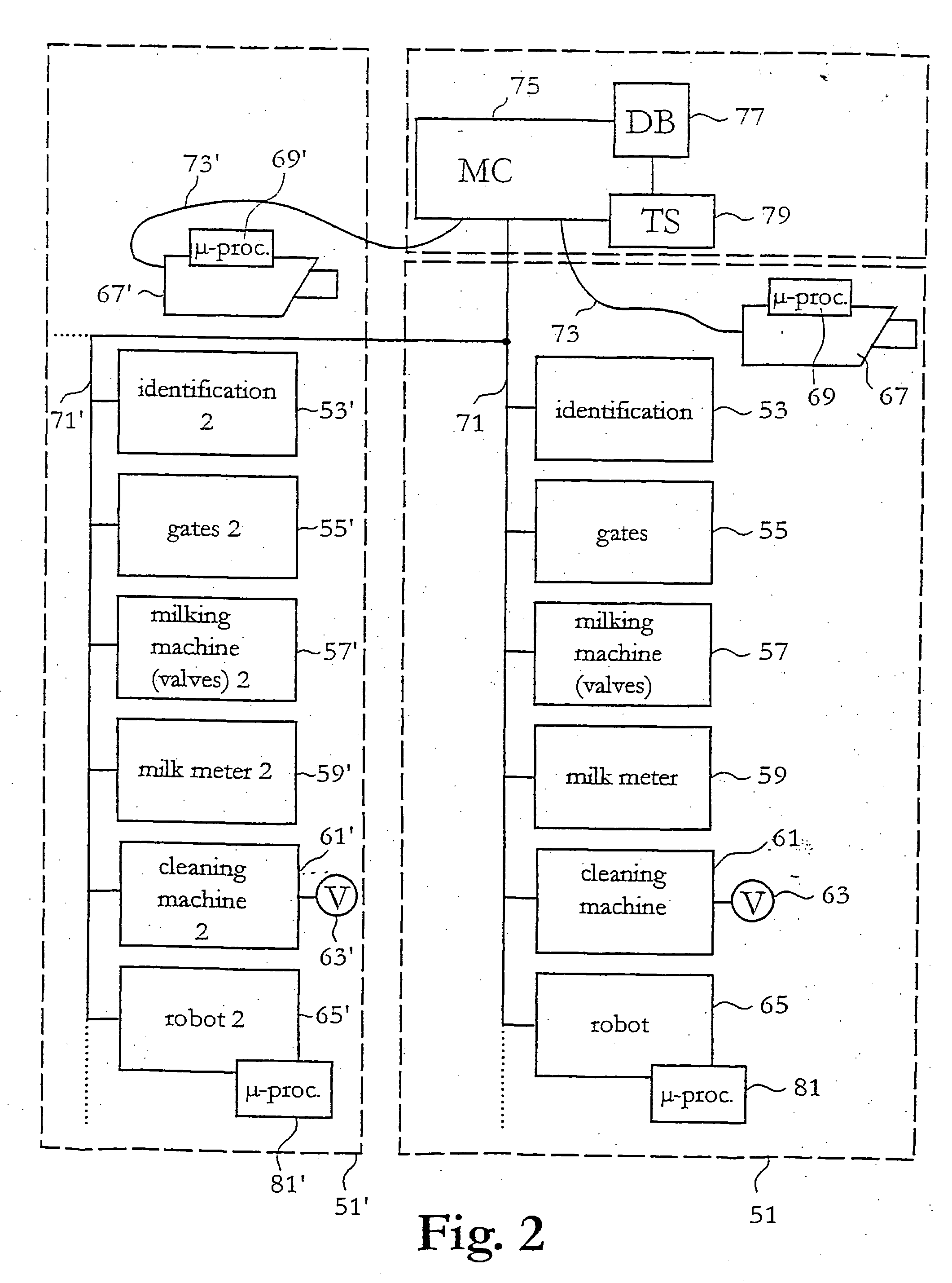
[0022] By the provision of a distributed modular milking system including a master computer for the overall control of the system and a slave processor at the robot for the detailed control of the robot movement the addition of further milking stalls to the system is facilitated. Such further milking stalls may each have its own robot provided with a slave-computer or all milking stalls may use a common robot.
[0025] Preferably, further equipment such as e.g. a milking machine or a cleaning machine may be provided with slave processors to further distribute the intelligence of the system locally and free resources of the master computer. Thus, a computer having lower processor capacity may be used as master computer, and more advanced algorithms may be used locally since these do not affect the resources of the master computer nor the traffic on the bus.
[0026] Such a distributed modular milking system with a plurality of equipment on a single serial bus provides for a high level of flexibility both as regards the addition of further milking stalls to the system and as regards the number and kind of equipment in a single stall. Further, such approach makes the milking system easy to maintain and trouble-shoot. Fewer longer cables are needed (only access to the bus is needed and not all the way to the master computer) and fewer connections at the master computer are required.

Problems solved by technology

A drawback of such a milking station is that the capacity thereof is limited since only one animal at a time can be milked.
A drawback of using two or more milking stations in an area intended to house a herd of milking animals is that there is no coordination between the milking stations and thus an animal, having recently been milked in one milking station, may present herself at another milking station and be allowed to be milked therein.
Such performance is neither optimal from a milk production point of view nor from animal health point of view.
Further, such approach makes the milking system easy to maintain and trouble-shoot.

Method used


Image

  • System and method for milking animals
  • System and method for milking animals
  • System and method for milking animals

Examples


Embodiment Construction

[0031] In the following description, for purposes of explanation and not limitation, specific details are set forth, such as particular techniques and applications in order to provide a thorough understanding of the present invention. However, it will be apparent to one skilled in the art that the present invention may be practiced in other embodiments that depart from these specific details.

[0032] With reference now to FIG. 2, which illustrates, in a schematic block diagram, a computer-controlled milking system a preferred embodiment of the present invention will be described. The invention is primarily focused on the control of the milking and how such control is distributed in the system. Thus, the description is not concerned with the design and detailed operation of each individual apparatus and device.

[0033] The system of FIG. 2 comprises a milking stall 51, which a cow may visit to be milked automatically. The milking stall 51 may have a design similar to the design of the mi...


PUM


Abstract

A milking system comprising a milking stall (1, 51), which an animal may visit to be milked automatically, said milking stall including an animal identifier (9, 53); a gate controller (7, 55) for opening an entry and exit gates (3, 5); a milking machine (11, 57), wherein the teat cups, during milking of a milking animal in said milking stall, are applied to the teats of the milking animal and are connected to vacuum (19, 63) such that milk can be drawn from the milking animal and be collected in the vessel; and a robot (13, 65) provided with a robot arm (21) and a gripper (23) for automatic application of the teat cups to the teats of the animal. The milking system features a master computer (75) adapted to hold a database (77) of milking animals capable of visiting the milking stall, to receive an identification of a milking animal from said animal identifier, and adapted to control the gate controller, the milking machine, and the robot depending on the received identification; wherein the robot includes a slave processor (81), connected to receive information from the master computer, according to which movement of the robot arm of the robot is to be performed, and adapted to control the robot to move the robot arm of the robot according to said received information.

Description

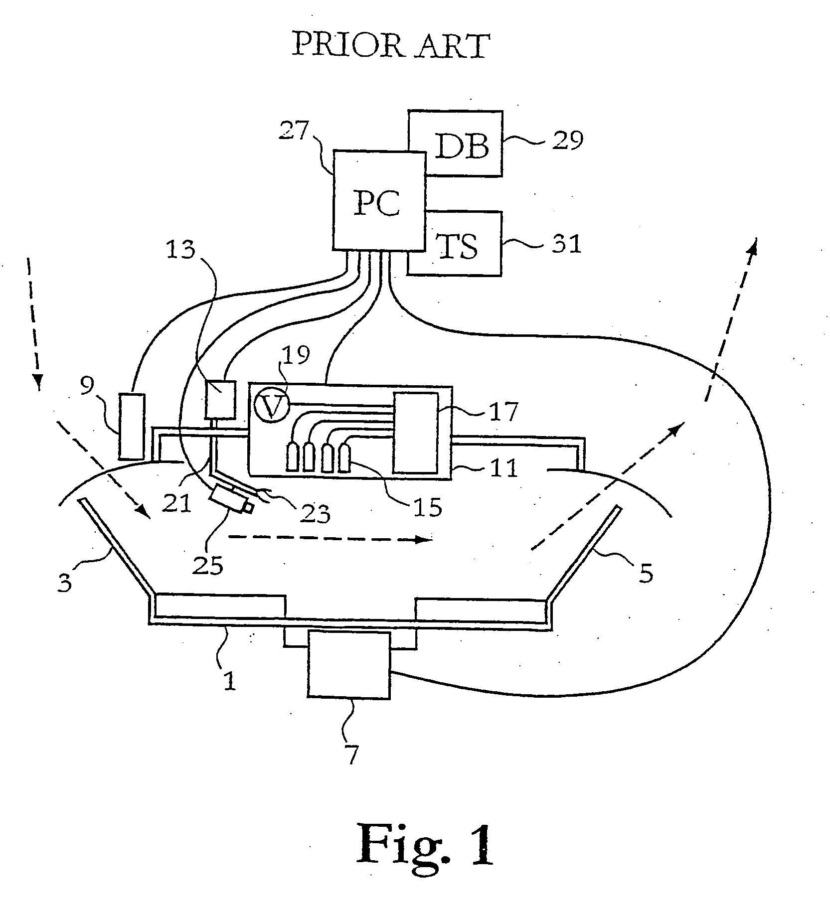
[0001] The present invention generally relates to dairy farming and particularly it relates to a computer-controlled system and a method, respectively, for milking animals.DESCRIPTION OF RELATED ART AND BACKGROUND OF THE INVENTION[0002] In modern dairy farm industry there are continuous research and development activities in order to improve the efficiency of various activities such as machine milking, which, inter alia, involves increased milk yield and reduced milking time.[0003] A major trend in this respect is an increased degree of automation of the various activities. For instance, machine milking may be performed completely automated by means of computer-controlled milking robots.[0004] A diagram of an automatic milking station is schematically illustrated in FIG. 1. A milking stall 1, which animals may visit on a voluntary basis to be milked, includes an entry gate 3 and an exit gate 5, respectively, which can be opened and closed by means of a gate opening / closing arrangeme...

Claims


Application Information

Patent Timeline
IPC IPC(8): A01J5/017A01K1/12
CPCA01K1/12A01J5/0175
Inventor SJOLUND, MARTINOSCARSSON, MATTIAS
Owner DELAVAL HLDG AB
Learn More