
Device for fixing a tube member

Inactive Publication Date: 2004-07-15
ALORO MEDICAL
View PDF7 Cites 19 Cited by
  • Summary
  • Abstract
  • Description
  • Claims
  • Application Information

AI Technical Summary

Benefits of technology

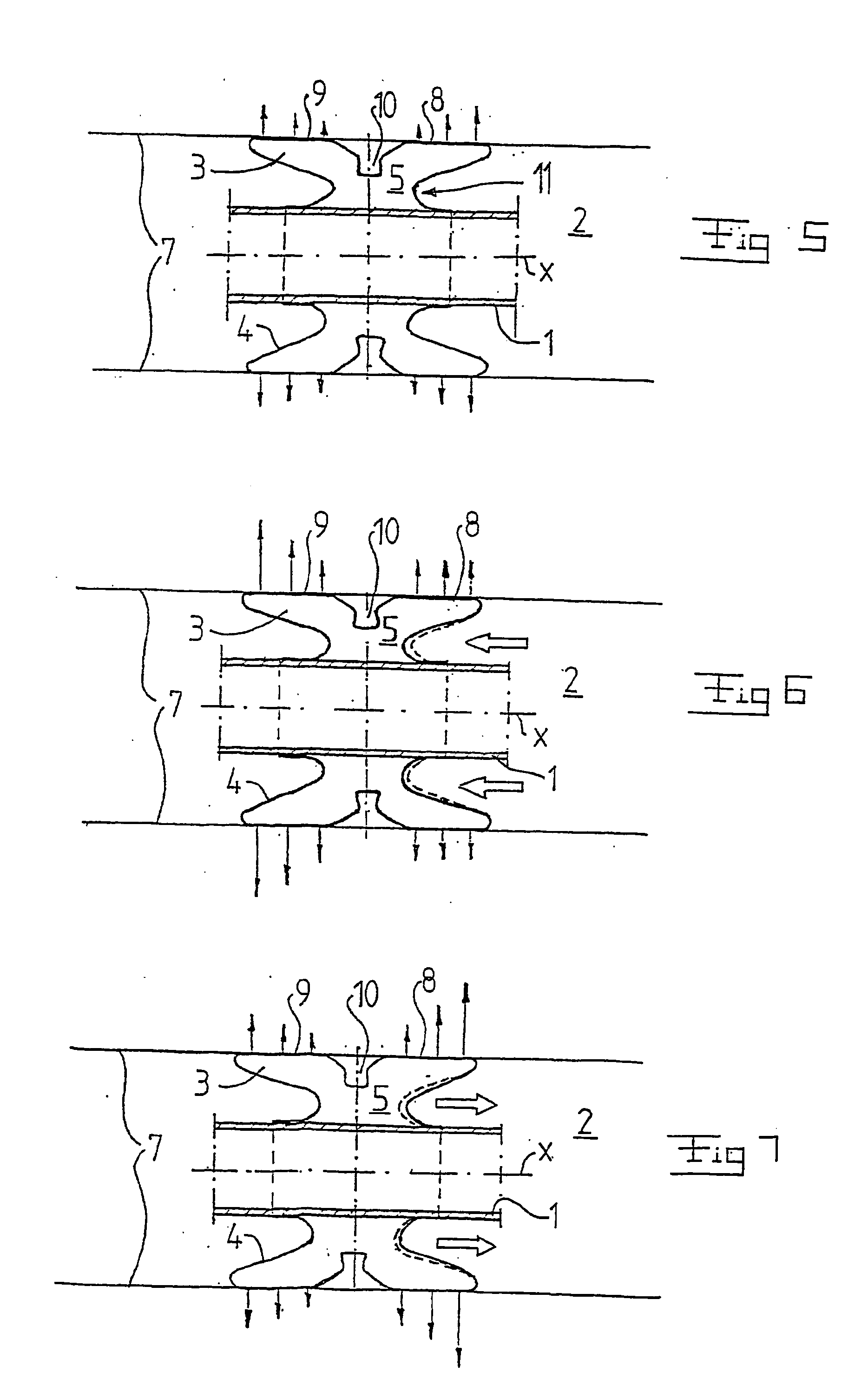
[0012] The contact pressure will, with such a design, be provided by the geometrical or structural shape of the body rather than by the working pressure prevailing in the inner space. This is a very important progress, since the inner working pressure will vary during use of the fixing device depending on the problems mentioned above regarding the diffusion of gas into and out of the inner space, the movement of the body in different directions in relation to the wall of the cavity, and the variation over time of the size of the cavity. The working pressure variations, which arise due to these causes, all lie within the normal working range. The present invention thus provides a fixing device, which has an improved sealing function in situations with non-shape permanent cavities and where external movements give an unfavourable influence of forces. At the same time it is possible, thanks to the substantial constant contact pressure, to reduce the risk of pressure injuries in various organic applications.
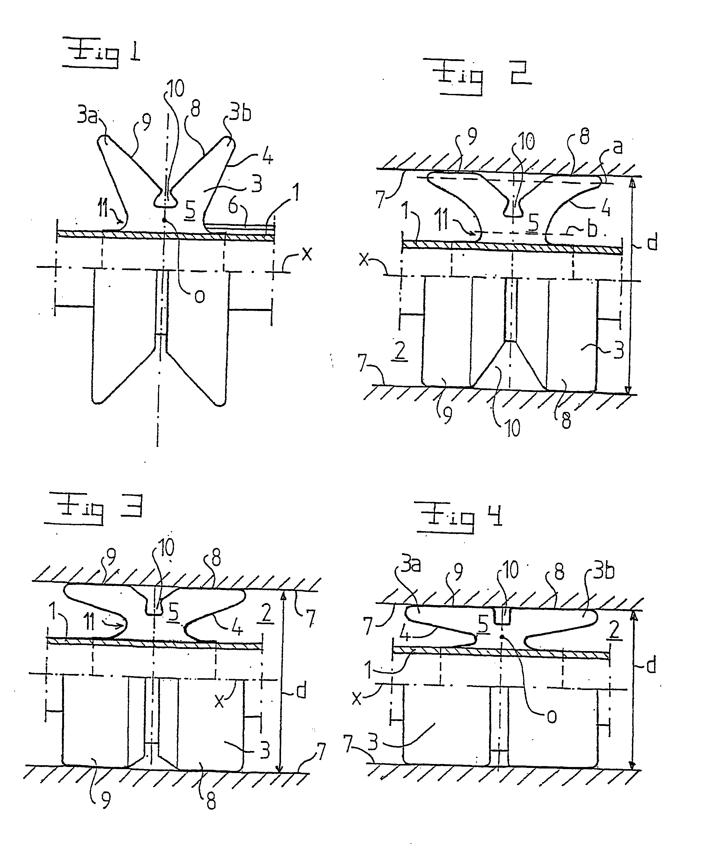
[0013] Such a body, which expands outwardly from the tube member, has a large flexibility and permits a tight continuous abutment at different radii of the cavity. Thanks to the shorter inner extension, the diameter of the outer extent of the body may vary with substantially the same contact pressure. Furthermore, the contact pressure may be kept constant if the working pressure increases or decreases since the length of the short extension may vary. The shorter extension also permits the contact surface to slope inwardly or outwardly with respect to a centre axis through the tube member, either with the same angle along the whole contact surface or with different angles for different portions. The fixing device according to the invention is thus very suitable for cavities where the wall of the cavity does not have a linear extension.
[0015] According to a further embodiment of the invention, the contact surface along the tube member is longer than said short extension. By such a contact surface, which is longer than the extension of the body in the proximity of the tube member, a proper sealing against the wall of the cavity is permitted. In that connection, the contact surface may advantageously include a first surrounding surface portion and a second surrounding surface portion, wherein these surface portions are separated from each other by a surrounding depression. By such a dividing of the contact surface into two portions, the flexibility of the body is further increased. The one surface portion may then, for instance, abut the cavity wall along another extension than the extension against which the other surface portion abuts. When the device according to the invention together with the tube member is introduced into the cavity and expanded, the geometrical shape, which the body would have taken in a freely expanded state, will be deformed when the body meets the resistance of the limiting wall of the cavity. However, the body will try to take back its original shape. By the design of the reduced portions, i.e. said short extension and in certain cases also said depression, one may obtain a desired size of the flexion resistance, which is desired to obtain. The flexion resistance is the contact pressure, which is transferred to the walls of the cavity, and it is, for a given design, relatively constant at different degrees of flexion. By the design according to the invention, it is rather the working pressure in the inner space, which will vary, due to external influences, without any substantial change of the contact pressure against the wall of the cavity. The reduced portions will also absorb the tendency to fold formation, which is present in such an expandable body, which means that the contact surface will lack all fold formation.
[0016] The geometrical shape of the body also contributes to the transfer of a direct external axial force influence on the casing to the walls of the cavity in a manner contributing to an increased security against leakage. After relief, the pressure against the wall is normalised again and such an intermittent loading and relief may in certain organic connections give a favourable "pulsation", which stimulates the blood supply to the peripheral tissue. Advantageously, the surrounding depression is designed in such a way that it does not abut said wall in the expanded state.

Problems solved by technology

Such an obstruction, which may appear if the contact pressure of the fixing member is too large, may rapidly result in serious consequences through the focal death of tissue.
The inflatable balloons used today are connected with problems with regard to leakage as well as tissue injuries.
Such leakage may be very serious, for instance in connection with a respirator treatment with the use of the endotracheal tube mentioned above.
If leakage arises, contaminated secretion from the upper airways may leak bypassing the balloon down to the sterile lungs and cause pneumonia.
During such treatment, pressure injuries on the tissue of the mucous membrane are also frequently present when using such balloons.
Consequently, it is difficult to maintain a consistent working pressure in the balloon.
Gas is diffusing outwardly, which decreases the pressure and increases the risk of leakage.
The relation is opposite when using certain anaesthetic gases, which contains nitrogen oxide, wherein the gas is flowing in an opposite direction and the working pressure within the balloon increases successively with a following risk of pressure injuries on the tissue.
Such folds lead to leakage and may also be irritating to the tissue.

Method used


Image

  • Device for fixing a tube member
  • Device for fixing a tube member
  • Device for fixing a tube member

Examples


second modified embodiment

[0039] FIG. 10 discloses the invention, according to which the body 3 has a long extension directly at the tube member 1 and a shorter extension at the line b in the proximity of the tube member 1. In the proximity of the outer extent, line a, the longitudinal extension is longer than at the line b, but shorter than directly at the tube member 1. In this embodiment, the inner space 5 is completely enclosed by the casing. The casing 4, and thus the body 3, is consequently displaceable on the tube member 1 in the direction of the centre axis x.

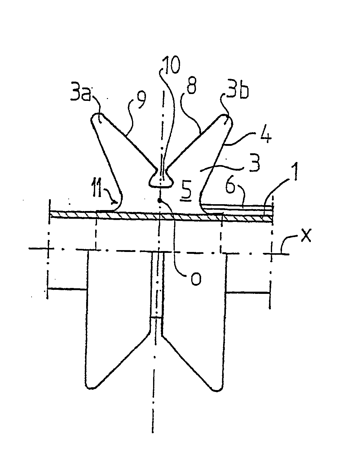
[0040] FIG. 11 discloses a third embodiment, which differs from the first and second embodiments in that the body 3 includes two separate body parts 3a and 3b, which both are attached to the tube member 1 at a distance from each other. Preferably, both body parts 3a, 3b are supplied with a fluid in such a way that substantially the same working pressure prevails in each body part 3a, 3b.


PUM


Abstract

The invention refers to a device for fixing a tube member (1) in a cavity (2) of a patient. The device includes a body (3), which surrounds the tube member and has a casing (4) that at least partly forms an inner space (5). The body (3) is expandable by supplying a fluid to the inner space in such a way that the fluid in the inner space has a working pressure. Furthermore, the body (3) has, in a non-expanded state, a relatively small outer extent, which permits the introduction into said cavity (2), and in an expanded state, a relatively large outer extend, which permits fixing in said cavity by abutment with a contact pressure against a tubular wall (7) of the cavity. In order to ensure a tight abutment against the wall (7) of the cavity, the body (3) has such a geometrical shape that the contact pressure is substantially constant independent of variations of the working pressure within a normal working range.

Description

THE BACKGROUND OF THE INVENTION AND PRIOR ART[0001] The present invention refers to a device for fixing a tube member in a cavity of a patient according to the initial portion of claim 1.[0002] By such tube members, it is in the present application referred to all types of pipes, which are intended to the introduced into a patient, i.e. a human being or an animal. It may for instance be so-called endotracheal tubes, which are intended to be introduced into the trachea, corresponding tubes for the introduction into the gullet, different types of hoses, cannulae, catheters etc. for various cavities of the patient.[0003] Frequently, it is desirable to fix such hoses or tube members in the cavities of the body of the patient in order to enable introduction and / or discharge of different fluids, i.e. liquids or gases. In that connection, the hose is to seal against an organic surface, which in its structure may be irregular as well as resilient. In order to obtain such a tight fixing, var...

Claims


Application Information

Patent Timeline
IPC IPC(8): A61M16/04A61M25/04
CPCA61M16/04A61M25/04A61M16/0459A61M16/0445A61M16/0436
Inventor FLODIN, BJORN
Owner ALORO MEDICAL
Learn More