Projection optical system, exposure apparatus, and device manufacturing method

a technology of projection optical system and exposure apparatus, which is applied in the direction of instruments, printers, therapy, etc., can solve the problems of low measurement precision of the surface shape of one or more mirrors, large size of a measuring machine such as an interferometer system required for measuring the curvature radius or shape of the reflection surface (aspherical surface) of the mirror, and large size of the measurement machine such as the interferometer system

Inactive Publication Date: 2004-07-15
CANON KK
View PDF8 Cites 8 Cited by
  • Summary
  • Abstract
  • Description
  • Claims
  • Application Information

AI Technical Summary

Problems solved by technology

If the curvature radius of a mirror is large, the size of a measuring machine such as an interferometer system required for measuring the curvature radius or shape of the reflection surface (aspherical surface) of the mirror becomes too large.
As described, in conventional projection optical systems, there is a problem that the m

Method used


Image

  • Projection optical system, exposure apparatus, and device manufacturing method
  • Projection optical system, exposure apparatus, and device manufacturing method
  • Projection optical system, exposure apparatus, and device manufacturing method

Examples


examples

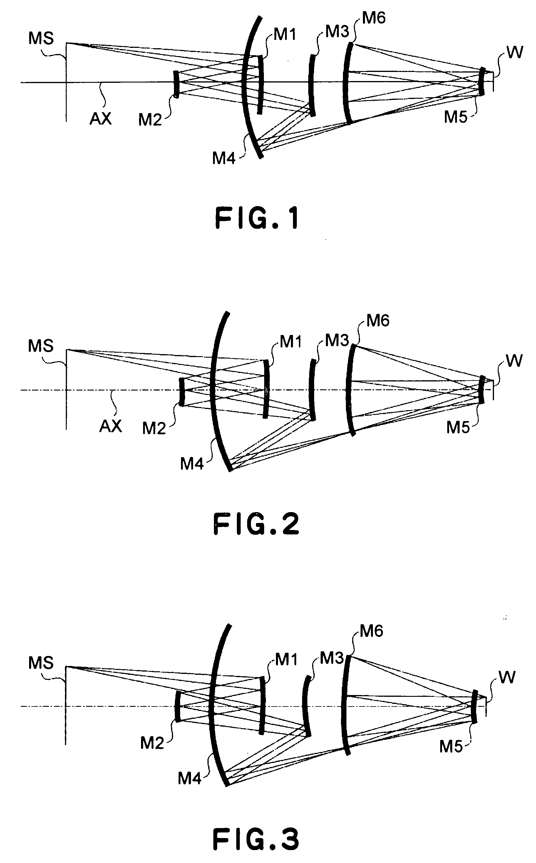
[0053] FIGS. 1-3 illustrate optical paths in section of Example 1, Example 2 and Example 3, respectively, of a projection optical system according to this embodiment of the present invention. In theses drawings, the same reference numerals are assigned to corresponding elements.

[0054] In FIGS. 1-3, denoted at MS is a reflection type reticle which is mounted at an object plane position. Denoted at W is a workpiece (wafer) to be exposed, and it is mounted at an image plane position. Denoted at M1 is a first mirror (concave mirror), and denoted at M2 is a second mirror (concave mirror). Denoted at M3 is a third mirror (convex mirror), and denoted at M4 is a fourth mirror (concave mirror). Denoted at M5 is a fifth mirror (convex mirror), and denoted at M6 is a sixth mirror (concave mirror). Denoted at AX is an optical axis.

[0055] As the reticle MS is illuminated with EUV light of a wavelength of about 13.5 nm, from an illumination optical system (not shown), in the projection optical sy...


PUM


Abstract

Disclosed is a projection optical system specifically to be used with extreme ultraviolet (EUV) light having a wavelength not less than 10 nm and not greater than 20 nm. The projection optical system has six mirrors sequentially reflecting light in an order from the object side toward the image side and being disposed to define a coaxial system, wherein each of the six mirrors has a curvature radius not greater than 1500 mm.

Description

FIELD OF THE INVENTION AND RELATED ART[0001] This invention relates to a projection optical system for projecting a pattern of a reticle in a reduced scale, by use of EUV (extreme ultraviolet) light. More particularly, the invention concerns a projection optical system for performing reduction projection by use of a plurality of mirrors, of a number of about six, for example.[0002] A projection optical system for performing reduction projection by use of mirrors of a number of about six, is disclosed in, for example, U.S. Pat. No. 5,686,728, No. 6,172,825 (Japanese Laid-Open Patent Application No. 2000-100694), or No. 6,353,470 (Japanese Laid-Open Patent Application No. 2000-235144).[0003] However, in the projection optical systems disclosed in these documents, one or more mirrors (in many cases, the first or second mirror in the order from the reticle side) have a curvature radius having a large absolute value, such as 1600 mm or more. In fact, in the examples among these projectio...

Claims


Application Information

Patent Timeline
IPC IPC(8): G02B17/06G02B17/08G03F7/20H01L21/027
CPCG03F7/70233G02B17/0657H01L21/027
Inventor SUZUKI, MASAYUKI
Owner CANON KK
Why Eureka
Try Eureka