
Pressure relieved thread connection

a thread connection and pressure relief technology, applied in the direction of hose connection, screw threaded joint, mechanical apparatus, etc., can solve the problems of high hydraulic force, damage to the threaded connection, and the problem of threaded connection also presenting problems

Inactive Publication Date: 2004-07-08
GRANT PRIDECO LP
View PDF12 Cites 41 Cited by
  • Summary
  • Abstract
  • Description
  • Claims
  • Application Information

AI Technical Summary

Benefits of technology

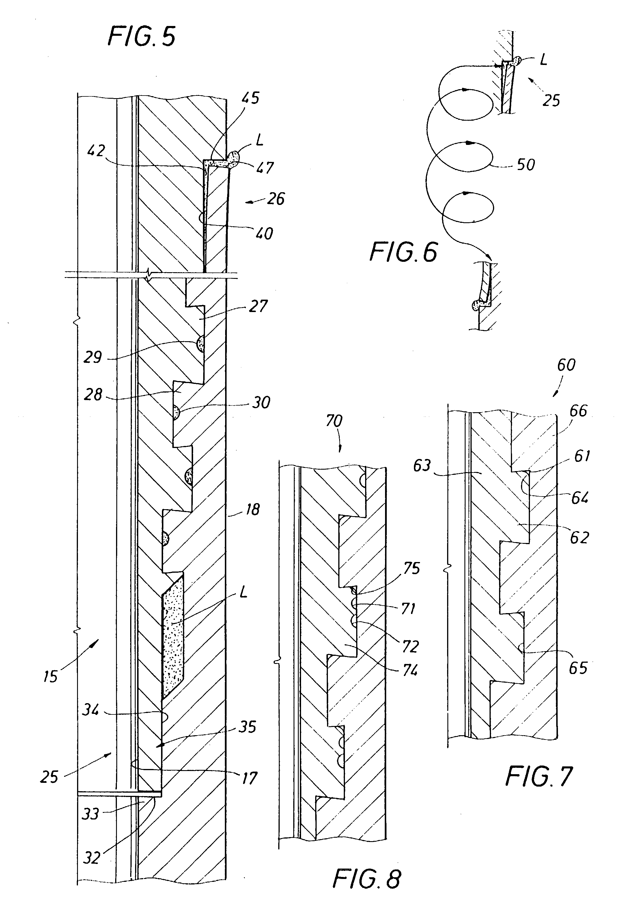
[0030] Grooves formed at the approximate midsection of the thread tooth crests provide a desired escape passage without reducing flank area contact of the engaged thread and without introducing significant stress risers in the thread form. In a modified form of the invention, the escape passage is formed by a bevel formed at the intersection of the thread tooth crest and the thread tooth flank. Both grooves and bevels may be used in the same connection to provide multiple flow passages.
[0031] Forming grooves in the thread teeth, rather than in the thread roots, provides the desired escape passage for trapped lubricant without introducing stress risers in the engaged components of the connection.
[0032] Forming the escape passage by bevelling the thread tooth has the advantage of providing the desired flow passage by modifying only the pin or box component of the connection.

Problems solved by technology

While the thread lubricant performs essential purposes in threaded connectors, its presence in certain types of threaded connections can also present problems.
Assembly procedures and impact loading can also compress the trapped thread lubricant causing extremely high hydraulic forces that can damage the threaded connection.
Certain desirable thread designs and thread forms are not readily employed in applications where trapped thread lubricant may be subjected to high pressures.
Wedge threads, dovetail threads, hooked threads and other complex thread forms that are well suited to perform desired mechanical holding and sealing functions in a threaded connector may be unsuitable for use in applications where trapped thread lubricant may become highly pressurized during the assembly or use of the connection.
Highly pressurized lubricant can also be problematic in the connectors used to assemble impact driven conductor pipe.
Jetting, however, is not always an available method of installing the conductor pipe.
However, threaded or other mechanical connections used to secure conductor pipe sections together are not inherently resistive to repetitive, impact loading.
For this reason, conductor pipes are not typically designed to withstand pressure differentials that may exist across the conductor wall.
However, as wells have become more challenging, the probability of a "kick" occurring in the conductor pipe has increased.
Such a kick may occur, for example, when the conductor pipe is driven into an abnormally pressured zone.
This combination of problems is of recent origin, having a genesis coincident with the advent of deeper, more challenging offshore drilling.
Moreover, while there are some conductor pipes that use an external elastomeric seal to restrict migration of seawater into the connection threads where it could cause corrosion or allow corrosion cracks to develop, the use of metal-to-metal seals for both an internal and external seal is not a common feature of conductor pipe design.
Conductor pipe connections designed to provide pressure tight seals using both internal and external metal-to-metal seals have an increased probability of encountering damaging stresses produced as a result of having high-pressure trapped lubricant in the connections.
Trapping an excessive amount of the thread compound between the internal and external seals can generate an enormous amount of hydraulic pressure between the pin and box as the volume containing the trapped fluid is decreased during the thread engagement process.
High impact loads applied during hammering of a conductor pipe are transferred across the engaged threads and can also produce high hydraulic pressures between the components of the connection.
The stresses from impact loading as well as the stresses induced by high hydraulic pressures between the connection components can cause a failure of the threaded connection in a conductor pipe.
Simple tight fitting thread forms do not offer adequate sealing when the pressures are high, especially when high temperatures are present.
One reason for this lack of universal acceptance by the end users of the pipe is that the wedging thread forms have uncontrollable makeup characteristics.
This is a very detrimental characteristic when trying to engage metal seal elements on the pin and the box because these elements are typically designed on a slight taper.
Therefore, if they are not accurately positioned relative to each other, they will not perform adequately when exposed to very high pressures.
The problem of unpredictable pin and box positioning when using wedging thread forms is due to several factors.
This tight fit can entrap lubricant to the extent that the lubricant can't escape during the makeup procedure, which can cause a hydraulic layer of lubricant to be trapped between the pin and box threads.
When this happens, the connection is further restricted from proper makeup position, which further hinders the proper engagement of the sealing elements.
A related problem resulting from trapping lubricant within a threaded connection is that the hydraulic forces in the lubricant resulting during makeup prevent the pipe assembly process from being accurately monitored.
The presence of trapped thread lubricant in the connection can produce an abnormal torque reading relative to the made up position of the connection.
The thread modifications taught by the '411 patent can compromise the efficiency of a threaded connection, particularly those connections in which engagement of the thread flanks is an essential part of the thread design.
Formation of a recess in the root area of a thread can, however, concentrate stresses acting on the threaded connection, adversely affecting its strength.

Method used


Image

  • Pressure relieved thread connection
  • Pressure relieved thread connection
  • Pressure relieved thread connection

Examples


Embodiment Construction

[0073] A conductor pipe string of the present invention is indicated generally at 10 in FIG. 1. The top end of the pipe string 10 is engaged by a hammer H that is being operated above the surface S of a body of water W. A mud line ML is at the interface between the earth E and the water body W. The string 10 is driven into the earth in reaction to repeated impact blows delivered by abrupt reciprocating movement of the hammer H.

[0074] The conductor pipe string 10 is constructed from the assembly of a number of conductor pipe sections such as the sections 11 and 12 connected together at their ends 13 to make a string of pipe that extends below the mud line ML to a desired subsurface point P. The point P may be the design depth for the well construction or may be the point of refusal at which the pipe can no longer be driven into the earth. As thus far described, the conductor pipe and installation process are conventional.

[0075] FIG. 2 of the drawings illustrates a form of a threaded ...


PUM


Abstract

Lubricant escape passages are formed in the threads used to connect one tubular body to another. The passages conduct trapped thread lubricant out of the threaded area to prevent the creation of high lubricant pressure that may damage or cause improper make up of the threaded connection. The passages may be grooves in the crests of the thread teeth and / or may be corner bevels on the thread teeth. In a conductor pipe or other pipe assembly using axially spaced internal and external seals at each axial end of the threaded area, the escape passages form a helical flow path through the engaged thread area. The external seal prevents the entry of corrosive fluids into the threaded area and the internal seal prevents leakage through the threaded area from within the conductor pipe. When the lubricant pressure increases excessively during assembly or impact loading of the connection, the lubricant escapes past the seals to prevent connection damage. When used with a wedge or other metal-to-metal thread engaging designs, the escape passages may be interrupted at some point intermediate their helical path to provide a pressure seal at the point of interruption. Relieving trapped lubricant from a wedge thread connection permits consistent final makeup positions that ensure optimal pressure sealing.

Description

[0001] The present invention relates generally to threaded connectors. More specifically, the present invention relates to the connection together of threaded tubular bodies wherein high pressures may be developed in the lubricant trapped in the overlapping threaded area connecting the bodies. In one specific application, the present invention relates to threaded connections in tubular bodies where the connection makeup process and / or impact loading of assembled connections produce damagingly high pressures in trapped lubricant within the overlapping threaded area of the connected members. In another specific application, the invention relates to thread lubricant trapped in connections using wedge-type threads.BACKGROUND SETTING OF THE INVENTION[0002] Pipe is inserted into the earth to perform tasks that are as diverse as the simple job of establishing building footings to the more complex task of constructing a deep offshore well. The pipe may be jetted into place using a washing o...

Claims


Application Information

Patent Timeline
Patent Type & Authority Applications(United States)
IPC IPC(8): E21B17/042E21B17/08F16L15/06
CPCE21B17/042F16L15/004E21B17/08
Inventor DELANGE, RICHARD W.TAYLOR, WOODWARD A.PARKER, CURTIS J.
Owner GRANT PRIDECO LP
Learn More