Lining device for a plate heat exchanger

Inactive Publication Date: 2004-06-17
ALFA LAVAL CORP AB
View PDF6 Cites 4 Cited by
  • Summary
  • Abstract
  • Description
  • Claims
  • Application Information

AI Technical Summary

Benefits of technology

[0007] Since no deformation of the material takes place in the two parts during the mounting of such a lining device, the risk of formation of cracks of the inner abutment portion is substantially reduced.
[0009] Furthermore, such a first part, which has a larger material thickness than the second part, permits that the second part during the welding is pressed against the first part so that possible air, and thus oxygen gas, between the parts is forced away. Consequently, the need of so called root gas, i.e. the supply of an inert gas, for instance argon, for displacing oxygen gas from this welding area is eliminated.
[0011] The time for the mounting of the lining device to the end plate is very short and the weld joint may advantageously be applied in an automatic manner.
[0015] According to a further embodiment of the invention, the pipe portion of the first part is introducible into said porthole from the outer side of the end plate and the pipe portion of the second part is introducible in said porthole from the inner side of the end plate. Such an embodiment is advantageous and permits the manufacturing of the first, outer part in one single piece of material with a relatively large material thickness and the second inner part in one single other piece of material with a relatively small material thickness.

Problems solved by technology

During certain conditions, problems can occur with the quality of the bent flange due to formation of cracks.

Method used


Image

  • Lining device for a plate heat exchanger
  • Lining device for a plate heat exchanger
  • Lining device for a plate heat exchanger

Examples


Embodiment Construction

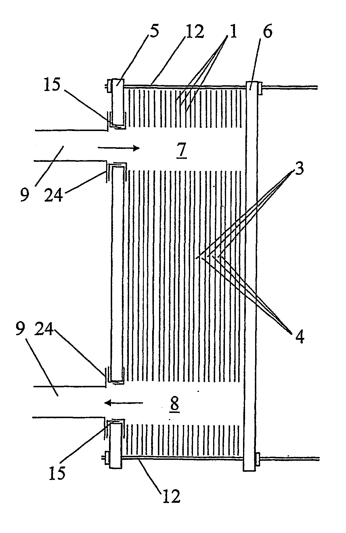
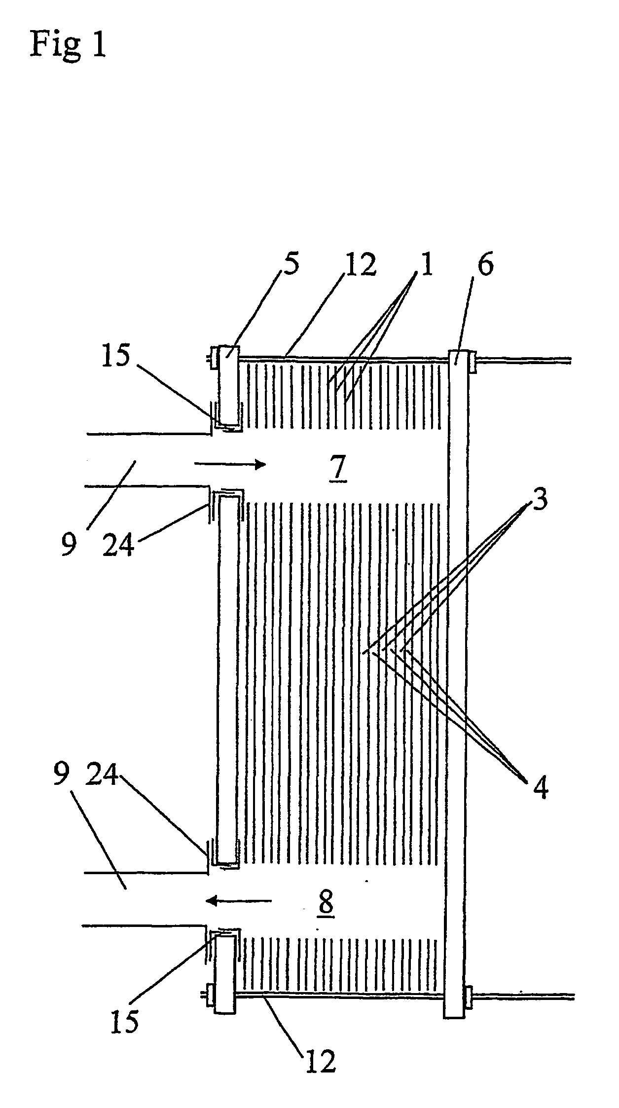
[0028] FIG. 1 discloses a plate heat exchanger according to a first embodiment of the invention. The plate heat exchanger includes a number of heat transfer plates 1, which form a plate package. The heat transfer plates 1 are pressed to such a shape that when they are arranged beside each other to said plate package, a plate interspace is formed between each pair of plates 1. The plate interspaces are arranged to form first passages 3 for a first fluid and second passages 4 for a second fluid. The first passages 3 are separated from the second passages 4. The plate heat exchanger includes also two end plates 5 and 6, between which the plate package is provided.

[0029] Furthermore, the plate heat exchanger includes four port channels 7, 8, two of which appear from FIG. 1. Each port channel 7, 8 extends through all plates 1 and at least one of the end plates 5, 6. Two of the port channels 7, 8 communicate with the first passages 3 and the two other port channels communicate with the se...


PUM

PropertyMeasurementUnit
Thicknessaaaaaaaaaa

Abstract

The invention refers to a lining device (15) for a plate heat exchanger, a plate heat exchanger, and a method for manufacturing a plate heat exchanger with a package of heat transfer plates and an end plate (5), which has at least one porthole. The lining device includes a first part (16) and a second part (17). Each of these parts is manufactured of a sheet metal and has a substantially cylindrically pipe portion (16a, 17a) and an abutment portion (16b, 17b). The pipe portion of the first part is introducible in the porthole and the pipe portion of the second part is introducible in the porthole into the pipe portion of the first part in such a way that an area (19) is formed where the pipe portions overlap each other. The parts are connected to each other by means of a weld joint (18). The material thickness of the first part is larger than the material thickness of the second part at least at said overlapping area.

Description

BACKGROUND OF THE INVENTION AND PRIOR ART[0001] The present invention refers to a lining device for a plate heat exchanger according to the preamble of claim 1, a plate heat exchanger according to the preamble of claim 8, and a method for manufacturing a plate heat exchanger including a package with heat transfer plates and an end plate, which has an outer side and an inner side facing the plate package and at least a porthole.[0002] It is known to provide the portholes of the end plates of a plate heat exchanger with a lining. According to a conventional method, a starting material is manufactured, which consists of a deep-drawn pipe portion and a flange portion extending around the pipe portion and substantially radially outwardly from the pipe portion at its one end. The other end of the pipe portion is introduced into and through the porthole of the end plate so that the flange portion abuts one side of the end plate. Thereafter, the other end of the pipe portion is bent outward...

Claims


Application Information

Patent Timeline
IPC IPC(8): B23K9/00B23K9/167B23K9/02B23K101/14F28F9/00F28F19/00
CPCF28F19/002Y10T29/4935Y10T29/49393
Inventor JONSSON, MATSANDERSSON, ANDERSSVENSSON, INGE
Owner ALFA LAVAL CORP AB
Why Eureka
Try Eureka