
Method and system for reducing engine induced vibration amplitudes in an aircraft fuselage

a technology of engine and fuselage, which is applied in the direction of active noise reduction system, rotocraft, power plant arrangement/mounting, etc., can solve the problems of significantly affecting (i.e. impairing or detracting from) the overall comfort of passengers in the aircraft, reducing effectiveness, and reducing passenger comfort. , to achieve the effect of improving the damping of elastic oscillating movement of the aircraft fuselage, improving flight comfort, and improving passenger comfor

Inactive Publication Date: 2004-06-03
SCHIERENBECK DETLEF
View PDF11 Cites 12 Cited by
  • Summary
  • Abstract
  • Description
  • Claims
  • Application Information

AI Technical Summary

Benefits of technology

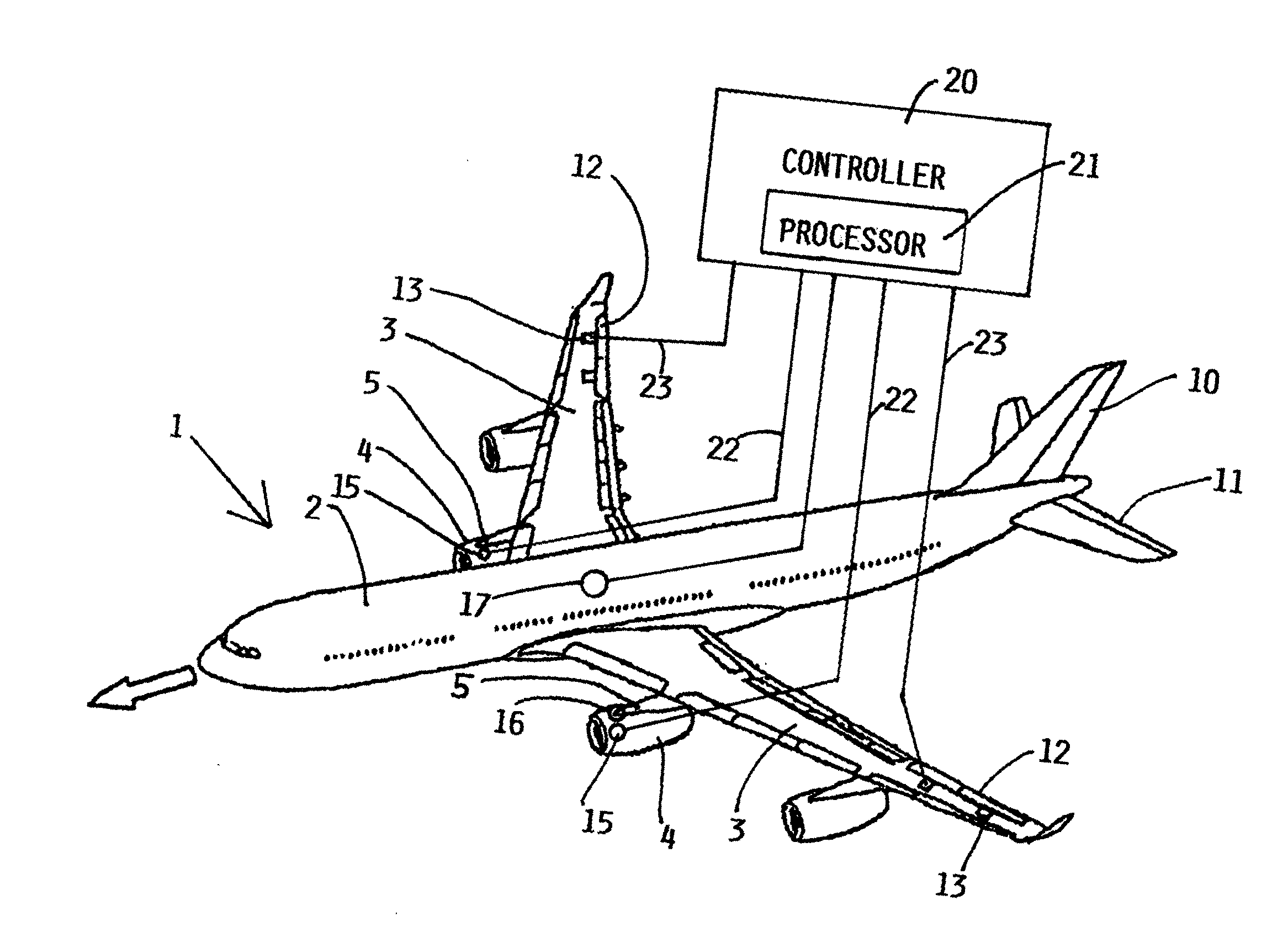
[0010] The above objects have further been achieved according to the invention in a method for reducing lateral and / or vertical vibration amplitudes that are induced in the fuselage of an aircraft by the engine dynamics of the operating engines of the aircraft, for the purpose of improving the flight comfort of the passengers in the aircraft. The method involves detecting engine induced vibrations using at least one acceleration sensor for sensing the lateral and / or vertical accelerations on or in at least one engine or at a forwardmost connection between an engine and an engine mounting pylon. The inventive method further comprises providing the measured acceleration signals as an input for executing a prescribed regulation rule set and thereby generating a control signal dependent on the acceleration signals, and providing this control signal to an actuator of an aileron mounted on the wing of the aircraft. By appropriately controlling the position of the aileron, the measured vibrational accelerations are counteracted, reduced, and / or damped out in an active manner.
[0012] In any event, use of the inventive method and system avoids the need for increasing the stiffness of the aircraft structure in an effort to reduce the engine induced vibrations or oscillations. Such stiffness alterations would be expensive, not very effective, and result in unacceptable increases of the weight of the aircraft.
[0014] As a principle advantage, the invention achieves a considerably improved passenger comfort through a drastic improvement of the damping of the elastic oscillating movements of the aircraft fuselage. Additional advantages of the invention include: a direct regulating or counteracting influence on the engine vibration amplitudes with a considerably improved flight comfort; regulation rules that are independent of the fuel level and the overall loading of the aircraft; a significant improvement of flight comfort for the passengers, independent of lateral and vertical accelerations in the fuselage of the aircraft; and avoiding the need to substantially alter existing hardware or systems of the aircraft, which would lead to an increased weight of the aircraft, because the inventive method and system can easily be incorporated in and used together with the conventional systems already existing in an aircraft.

Problems solved by technology

Additionally, such vibrations can be induced in the aircraft fuselage due to the influence of wind gusts and the like.
In these high capacity stretched aircraft fuselages, the arising vibrations and / or oscillations can significantly influence (i.e. impair or detract from) the overall comfort of passengers in the aircraft during flight.
In these conventional systems, the vibrations and / or oscillations induced by the operation of the engines are only indirectly detected and influenced by the control of the elevators and rudder, with a corresponding reduced effectiveness, because the engine-induced vibrations are measured only indirectly, as a component of the overall vibrations of the fuselage, by the accelerometers arranged in the fuselage.
As a result, the sensitivity or precision of the regulation is further diminished as the fuel level and overall loading of the aircraft varies.
There are various other known methods and systems for sensing and then reacting to varying loads that act on the aircraft during flight and can cause vibrations or oscillations thereof, especially with regard to wind gust loads acting on the aircraft for example.
The known conventional methods and systems in this context do not address and are not suitable for reducing vibration and oscillation amplitudes that are induced in the aircraft fuselage by the operation dynamics of the engines.
Such stiffness alterations would be expensive, not very effective, and result in unacceptable increases of the weight of the aircraft.
This results in an unsymmetrical aircraft vibration or oscillation behavior.

Method used


Image

  • Method and system for reducing engine induced vibration amplitudes in an aircraft fuselage
  • Method and system for reducing engine induced vibration amplitudes in an aircraft fuselage

Examples


Embodiment Construction

[0016] The single drawing FIGURE schematically shows an aircraft 1, including a fuselage 2, and two wings 3 protruding to the right and left sides of the fuselage 2. The aircraft 1 further includes various control surfaces such as a rudder 10, elevators 11, as well as ailerons 12 provided on the trailing edges of the wings 3. The ailerons 12 are actuated and controlled with respect to their deflection position by any conventionally known arrangement of actuators 13. The aircraft 1 further includes engines 4, such as any typical jet turbine engines, mounted by pylons 5 onto the wings 3. The just-described general components of the aircraft 1 may have any conventionally known design, construction, arrangement and operation. The special features of the inventive system in the aircraft 1 will be described next.

[0017] The inventive system includes a controller 20 incorporating a computer processor 21, which may be embodied in the existing flight control computer of the aircraft 1. The co...


PUM


Abstract

Vertical and / or lateral acceleration sensors are mounted in or on the engines or pylons of an aircraft to measure the vibrations induced by the operating dynamics of the engines. The sensors provide measured vibration signals to a controller that generates control signals in response to and dependent on the measured vibration signals. The control signals are provided to the aileron actuators, so as to actuate the ailerons appropriately to counteract and thereby reduce the engine-induced vibrations. Thus, the engine-induced vibrations acting on the fuselage are diminished and the passenger flight comfort is significantly improved.

Description

PRIORITY CLAIM[0001] This application is based on and claims the priority under 35 U.S.C. .sctn.119 of German Patent Application 102 36 815.5, filed on Aug. 10, 2003, the entire disclosure of which is incorporated herein by reference.[0002] The invention relates to a method and an arrangement or system for reducing the amplitudes of lateral and / or vertical vibrations and / or oscillations (generally called vibrations herein) induced in the fuselage of an aircraft by the operating dynamics of the engines of the aircraft.BACKGROUND INFORMATION[0003] The operating engines of an aircraft must be considered as gyroscopic systems that exhibit various operating dynamics due to the rotating masses of the internal components and mechanisms of the engines. In turn, the fuselage of the aircraft exhibits a dynamic response characteristic to the operating dynamics of the engines, whereby vibrations and / or oscillations (generally called simply vibrations herein) are induced in the aircraft fuselage...

Claims


Application Information

Patent Timeline
IPC IPC(8): B64D27/00F16F15/02
CPCB64D27/00B64C2220/00F16F15/02
Inventor SCHIERENBECK, DETLEF
Owner SCHIERENBECK DETLEF
Learn More