Modeling miller effect in static timing analysis

a technology of static timing analysis and miller effect, which is applied in the direction of resistance/reactance/impedence, program control, instruments, etc., can solve the problems of complex and time-consuming analysis, inability to accurately reflect the delays experienced, and inability to accurately model the static timing data of the wir

Inactive Publication Date: 2004-05-27
AVAGO TECH WIRELESS IP SINGAPORE PTE
View PDF3 Cites 8 Cited by
  • Summary
  • Abstract
  • Description
  • Claims
  • Application Information

AI Technical Summary

Problems solved by technology

Unfortunately, the static RC data for a wire may not accurately reflect the delays experienced on that wire.
This approach may help account for Miller effect, but may be complex and time consuming.
Furthermore, for high frequency integrated circuit designs, the timing windows may overlap substantially, further complicating the analysis.
Such a rule of thumb approach may not provide a very accurate Miller effect accounting for a given wire.

Method used


Image

  • Modeling miller effect in static timing analysis
  • Modeling miller effect in static timing analysis
  • Modeling miller effect in static timing analysis

Examples


Embodiment Construction

Design Flow Overview

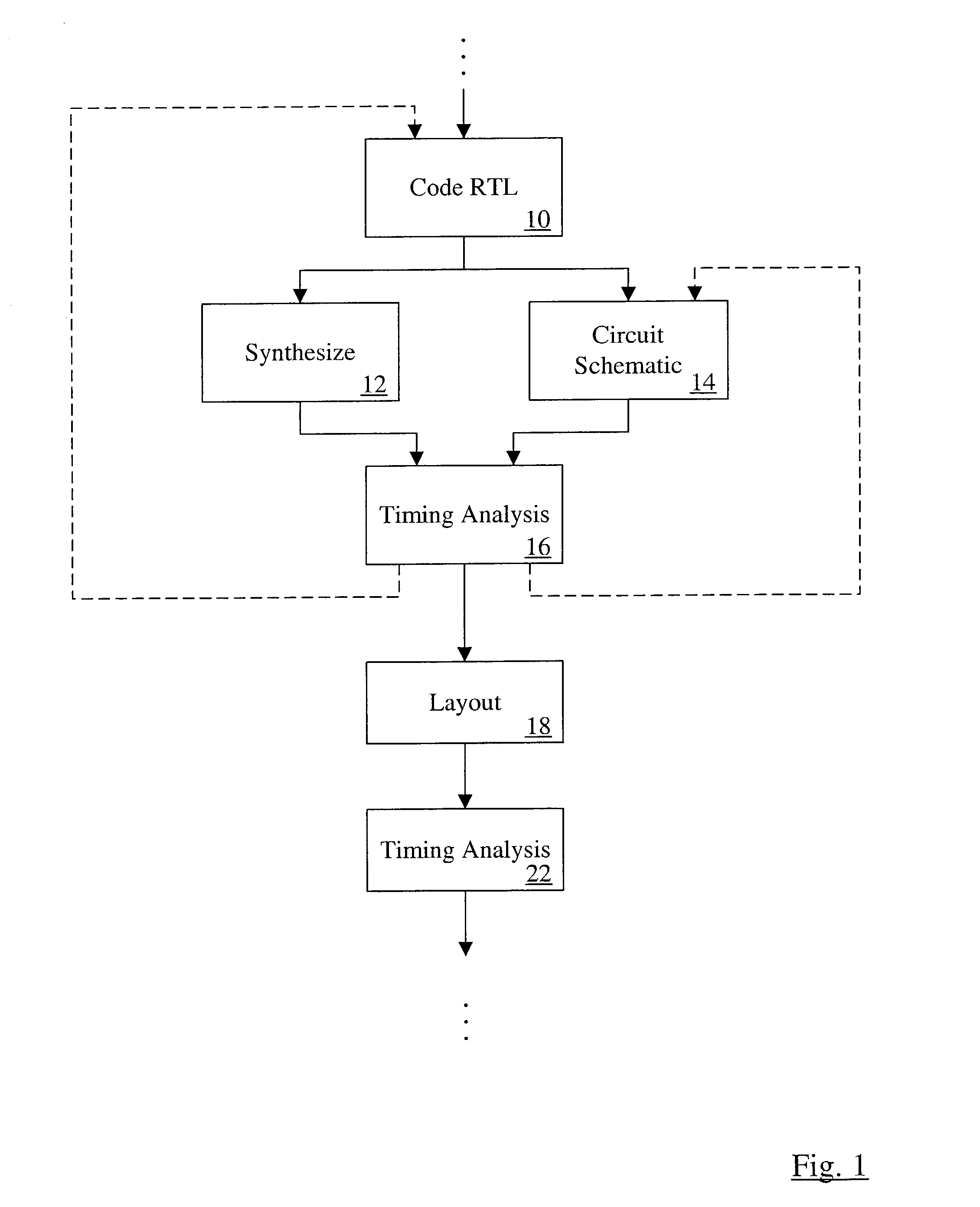
[0021] Turning now to FIG. 1, a block diagram illustrating one embodiment of a portion of a design flow is shown.

[0022] Once the integrated circuit design has been divided into one or more blocks of functionality (more briefly referred to herein as partitions), the designer may code a register-transfer level (RTL) description of each partition (reference numeral 10). Any hardware design language (HDL) may be used as the language for the RTL description (e.g. VHDL, Verilog, etc.). The RTL description may comprise one or more files per partition, as desired.

[0023] The designer may choose to use a synthesis tool to synthesize the RTL description to a netlist (reference numeral 12). The synthesis tool takes the RTL description and a library of cells (predesigned circuits which have one or more inputs and produce one or more outputs as a specified function of one or more inputs) and generates a netlist of cells, linked together in such a way as to provide the function...


PUM


Abstract

A method is contemplated. According to the method, capacitances in a first resistance/capacitance (RC) extraction corresponding to a circuit are modified. Each capacitance is modified to estimate Miller effect on that capacitance. A ratio of a total capacitance on a first wire after the modification in the first RC extraction to a total capacitance on the first wire before the modification in the first RC extraction is calculated. Capacitances in a second RC extraction that are coupled to the first wire are modified according to the ratio. The second RC extraction is a reduced extraction as compared to the first RC extraction. A timing analysis is performed for the circuit using the second RC extraction with capacitances modified to estimate Miller effect.

Description

[0001] 1. Field of the Invention[0002] This invention is related to the field of integrated circuit development methodologies and, more particularly, to static timing analysis.[0003] 2. Description of the Related Art[0004] Static timing analysis tools are generally used in integrated circuit development methodologies to estimate the timing characteristics of a circuit being developed. The maximum frequency of operation of the circuit may be estimated by assuming "worst case" delays in the circuit elements (that is, the longest delays expected to be experienced in the fabricated integrated circuit, accounting for such factors as process variation, temperature variation, supply voltage variation, etc.). Additionally, proper operation for setup and hold times for clocked storage devices or circuit input / output signals may be estimated using "best case" assumptions for delays in the circuit elements (that is, the shortest delays expected to be experienced, accounting for the above facto...

Claims


Application Information

Patent Timeline
Patent Type & Authority Applications(United States)
IPC IPC(8): G01R27/26G01R27/28G06F17/50
CPCG06F17/5036G06F17/5031G06F30/3312G06F30/367
Inventor RAMARAO, KUMARSWAMYPAGE, MATTHEW J.
Owner AVAGO TECH WIRELESS IP SINGAPORE PTE
Why Eureka
Try Eureka