Surface acoustic wave filter, and antenna duplexer and communication equipment using the same
a technology of acoustic wave filter and a duplexer, which is applied in the direction of piezoelectric/electrostrictive/magnetostrictive devices, electrical apparatus, impedence networks, etc., can solve the problems of increasing the insertion loss in this band, insufficient attenuation, and transmission signals may be lost in the antenna duplexer
- Summary
- Abstract
- Description
- Claims
- Application Information
AI Technical Summary
Benefits of technology
Problems solved by technology
Method used
Image
Examples
embodiment 1
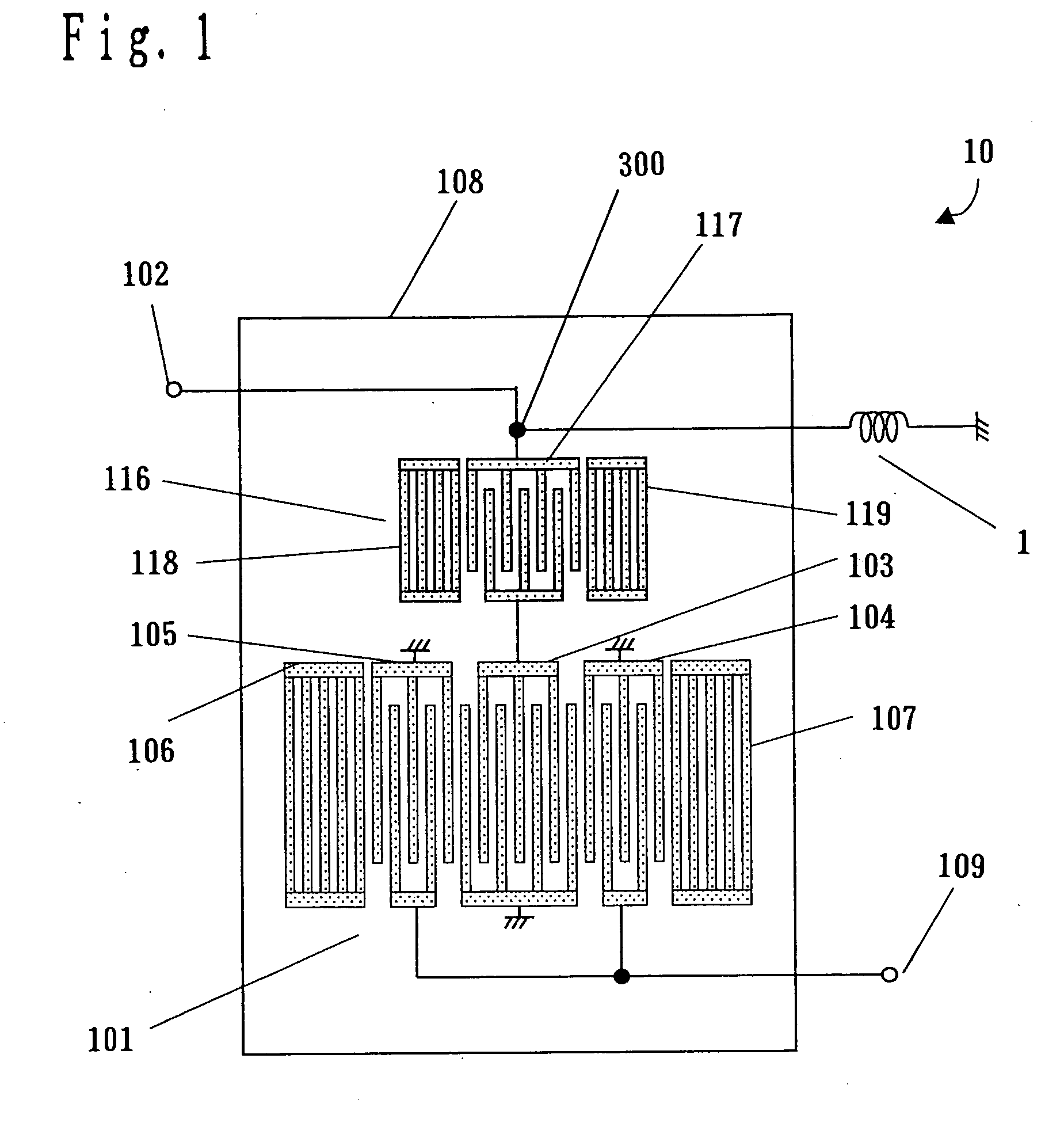
[0110] With reference to FIG. 1, description will be given of a configuration of a surface acoustic wave filter 10 according to Embodiment 1 of the present invention. In the surface acoustic wave filter 10, shown in FIG. 1, the same components as those of the conventional surface acoustic wave filter 130, shown in FIG. 27, are denoted by the same reference numerals. Their description is thus omitted.
[0111] The configuration of the surface acoustic wave filter 10 according to Embodiment 1 differs from the configuration of the conventional surface acoustic wave filter 130 in that a terminal 102 of a surface acoustic wave filter 116 is provided with an inductor 1 having one end grounded.
[0112] As shown in FIG. 1, the inductor 1 has one end connected to a connection point 300 between a bus bar side of an IDT electrode 117 and the terminal 102, and the other end grounded. That is, the inductor 1 is connected to an upper bus-bar side of the IDT electrode 117, i.e. a side at the connection...
embodiment 2
[0133] FIG. 14 is a plan view showing a surface acoustic wave filter 40 according to Embodiment 2 of the present invention. Components of the surface acoustic wave filter 40 that are the same as or correspond to those in FIG. 1 are denoted by the same reference numerals. Their detailed description is omitted. The surface acoustic wave filter 40, shown in FIG. 14, comprises the longitudinal coupled mode type surface acoustic wave filter 101 of the surface acoustic wave filter 10 according to Embodiment 1, as well as a surface acoustic wave resonator 131 further cascaded to the surface acoustic wave resonator 116, the inductor 1 having one end grounded and provided at a connection point 320 between the surface acoustic wave resonator 116 and a surface acoustic wave resonator 131, and an inductor 11 having one end grounded and provided at a connection point 330 between the terminal 102 and the surface acoustic wave resonator 131. That is, the present embodiment differs from Embodiment ...
embodiment 3
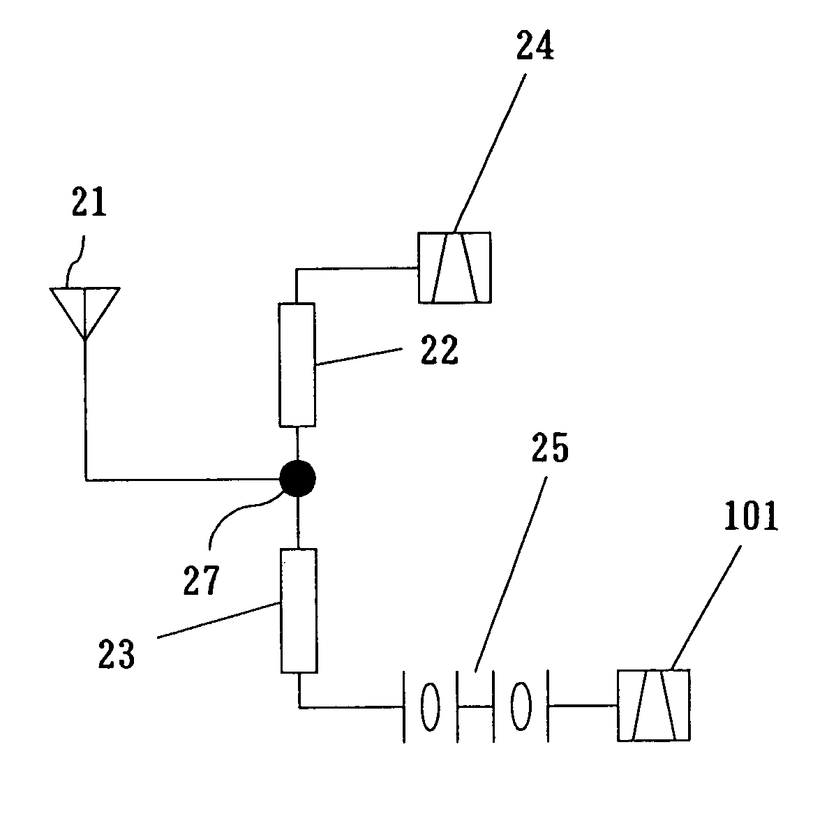
[0139] FIG. 17(a) is a block diagram showing a surface acoustic wave filter according to Embodiment 3 of the present invention and an antenna duplexer using the surface acoustic wave filter. In FIG. 17(a), a resonator 25 is the surface acoustic wave resonator 116 according to Embodiment 1 or 2 or a series circuit comprising the surface acoustic wave resonator 116 and the surface acoustic wave resonator 131. An output side of the resonator 25 is connected to the longitudinal coupled mode type surface acoustic wave filter 101. An input side of the resonator 25 is connected to one end of a phase circuit 23 as an example of a first phase circuit according to the present invention. The other end of the phase circuit 23 is connected via an antenna terminal 27 to an antenna 21 and one end of a phase circuit 22 as an example of a second phase circuit according to the present invention. The other end of the phase circuit 22 is connected to one end of a transmission filter 24. Reception means...
PUM
 Abstract
Description
Claims
Application Information
 - R&D
- Intellectual Property
- Life Sciences
- Materials
- Tech Scout
- Unparalleled Data Quality
- Higher Quality Content
- 60% Fewer Hallucinations
Browse by: Latest US Patents, China's latest patents, Technical Efficacy Thesaurus, Application Domain, Technology Topic, Popular Technical Reports.
© 2025 PatSnap. All rights reserved.Legal|Privacy policy|Modern Slavery Act Transparency Statement|Sitemap|About US| Contact US: help@patsnap.com


