Fluid control valve

a fluid control valve and valve body technology, applied in the direction of valve operating means/release devices, fuel injecting pumps, machines/engines, etc., can solve the problems of complex assembly of individual parts and high cos

Inactive Publication Date: 2004-04-01
ROBERT BOSCH GMBH
View PDF5 Cites 11 Cited by
  • Summary
  • Abstract
  • Description
  • Claims
  • Application Information

AI Technical Summary

Benefits of technology

[0005] The valve for controlling fluids of the invention having the characteristics of the main claim has the advantage over the prior art that a nozzle lock nut for bracing the individual parts can be dispensed with. The valve piece, the shim, and the nozzle body are joined to one another by at least two screws. The screws are disposed radially to the center axis of the valve. This makes a central disposition of the piezoelectric element also possible. In comparison with the prior art, the body disposed in the holder, for receiving part of the hydraulic booster, can be integrated with the valve piece, making it possible to reduce the number of component parts. Moreover, good radial centering of the shim relative to the valve piece is furnished, without requiring additional machining operations on the two individual parts. As a result, the angular tolerance between injection ports and clamping faces of the holder is also reduced. Moreover, the valve of the invention makes it possible to furnish a larger installation space for the valve member, making an optimal disposition of the valve member possible. Also in comparison with the nozzle lock nut of the prior art, the screws can be secured with greater tightening forces, without adverse effects on the positional precision of the individual parts of the valve.[0006] In a preferred feature of the present invention, the holder as well is joined to the valve piece, the shim and the nozzle body via the screws.[0007] In another advantageous feature of the invention, the holder is joined to the valve piece by means of welding. The result particularly in the holder is a larger installation space for the individual parts of the valve to be received therein. Moreover, screws with a larger diameter can also be used. As a result, a greater prestressing force can be exerted by the screws, and the number of screws can be reduced.[0008] Advantageously, the piezoelectric actuator is disposed centrally in the valve. This makes for an especially simple design of the valve of the invention.[0009] Advantageously, the hydraulic booster is also disposed centrally in the valve. In particular, this makes it possible to simplify the radial orientation between the first and the second seat.[0010] To enable a concealed disposition of the head of the screw, a recess is preferably provided in the nozzle body, or in the holder, or in the valve piece.[0011] A disk is advantageously provided for radially sealing off the nozzle body from the motor.

Problems solved by technology

However, this assembly of the individual parts is very complicated and quite expensive.

Method used


Image

  • Fluid control valve
  • Fluid control valve
  • Fluid control valve

Examples


Embodiment Construction

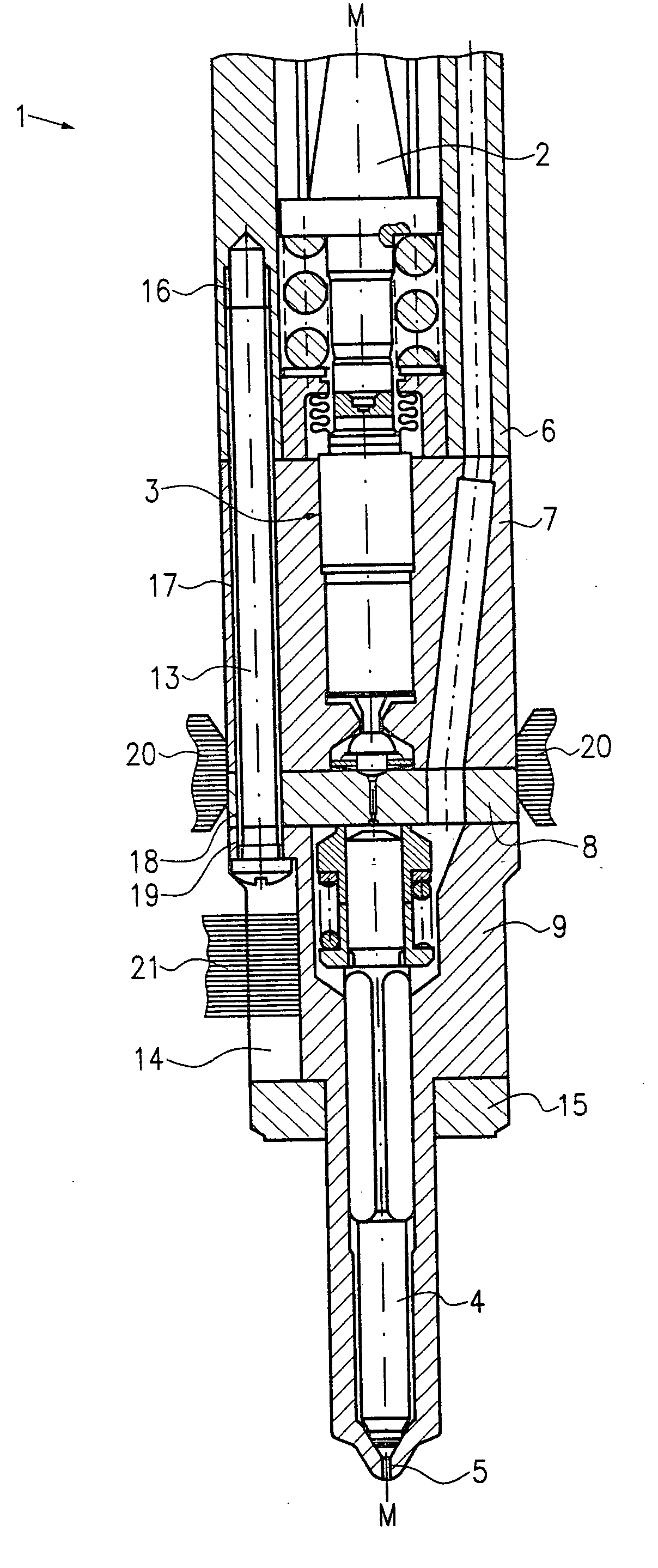
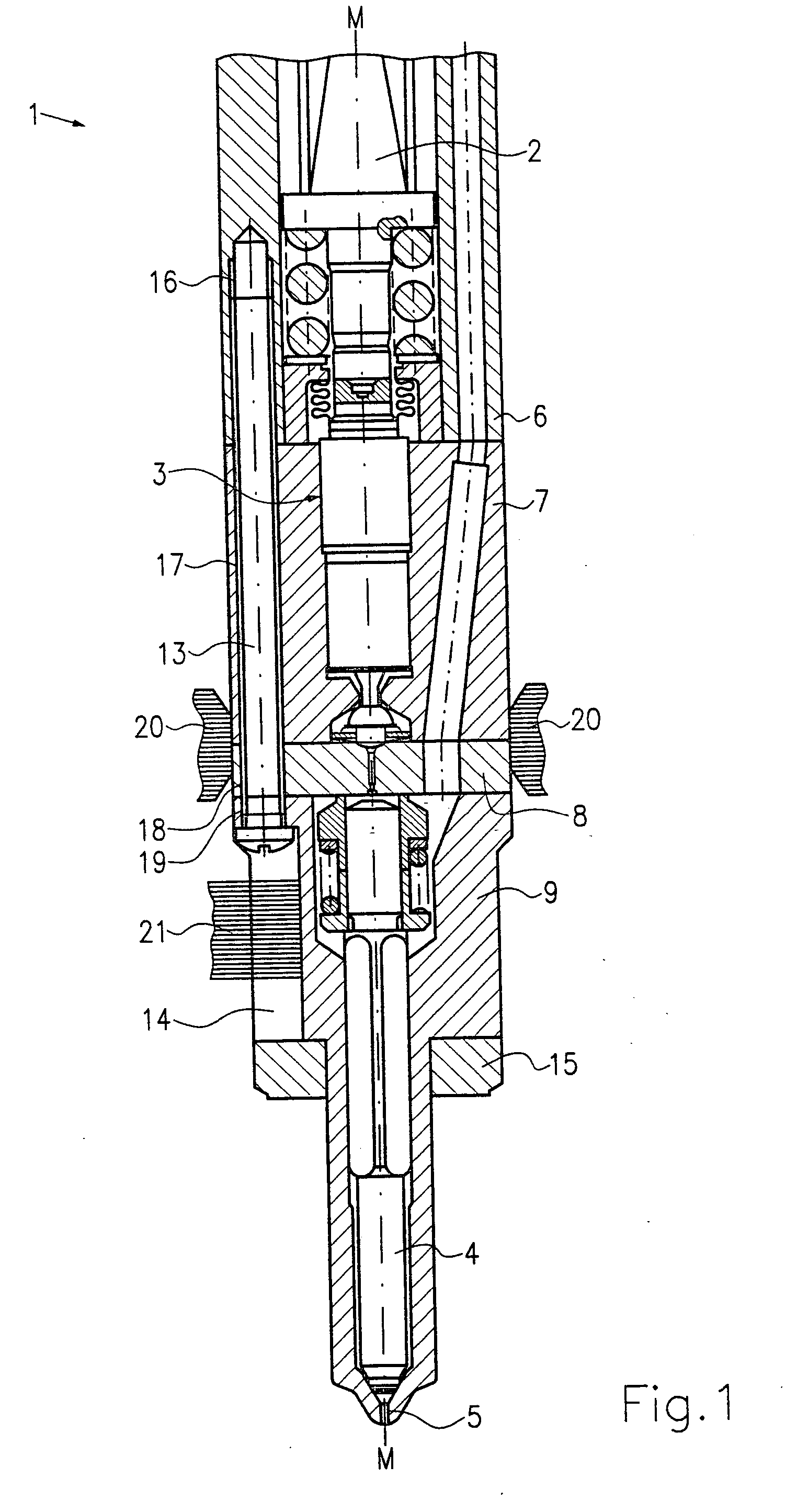
[0017] In FIG. 1, a first exemplary embodiment of a valve for controlling fluids of the present invention is shown.

[0018] As shown in FIG. 1, the valve 1 includes a valve member 4, which is actuatable via both a piezoelectric actuator 2 and a hydraulic booster 3. The valve member 4 closes and opens an inlet opening 5, through which fuel is delivered to a combustion chamber.

[0019] As shown in FIG. 1, the valve 1 includes a holder 6, a valve piece 7, a shim 8, and a nozzle body 9 in which the valve member 4 is disposed. The holder 6, valve piece 7, shim 8 and nozzle body 9 are joined together by two screws 13. For the sake of clearer illustration of the valve 1, only one screw 13 is shown in FIG. 1. More precisely, a threaded bore 16 is provided in the holder 6, a threaded bore 17 is provided in the valve piece 7, a threaded bore 18 is provided in the adapter 8, and a threaded bore 19 is provided in the nozzle body 9, each bore receiving the screw 13.

[0020] To make it easier to screw ...


PUM


Abstract

The present invention relates to a valve for controlling fluids, which includes a valve member (4) that is actuatable via a piezoelectric actuator (2) and a hydraulic booster (3). The valve further includes a holder (6), a valve piece (7), a shim (8), and a nozzle body (9). The valve piece (7), the shim (8), and the nozzle body (9) are joined together via at least two screws (13), and the screws (13) are disposed radially to a center axis (M-M) of the valve. This makes both a simple design of the valve and economical assembly possible.

Description

PRIOR ART[0001] The present invention relates to a valve for controlling fluids as generically defined by the preamble to claim 1.[0002] Valves for controlling fluids are known in the most various embodiments. For instance, in FIGS. 3 and 4, a valve for controlling fluids is shown which has a valve member 4 that is actuatable via a piezoelectric actuator 2 and a hydraulic booster 3. The valve further includes a holder 6, a valve piece 7, a shim 8, and a nozzle body 9. As shown in FIG. 3, the hydraulic booster here is disposed partly in the holder 6, in the valve piece 7 and the shim 8 offset from a center axis M-M of the valve. The hydraulic booster 3 furthermore has a first seat 11 and a second seat 12. A cylinder of the hydraulic booster is disposed in a body 23. As also visible in FIG. 3, the piezoelectric actuator 2 is disposed offset from the center line M-M. The individual parts of the valve 1, that is, the holder 6, valve piece 7, shim 8 and nozzle body 9, are secured to one ...

Claims


Application Information

Patent Timeline
Patent Type & Authority Applications(United States)
IPC IPC(8): F02M47/02F02M51/06F02M59/46F02M61/16F02M61/20F02M63/00F16K31/00F16K31/02F16K31/06
CPCF02M47/027F02M61/168F16K31/007F02M2200/21F02M61/20
Inventor STOECKLEIN, WOLFGANGSCHMIEDER, DIETMAR
Owner ROBERT BOSCH GMBH
Why Eureka
Try Eureka