
Addressing scheme supporting variable local addressing and variable global addressing

a global address and local address technology, applied in the field of multi-node system address space, can solve the problems of complex sharing of local memory or i/o devices with other nodes, creating complexities for software executing on the system, and allowing other nodes to grant the other nodes

Inactive Publication Date: 2004-03-04
AVAGO TECH INT SALES PTE LTD
View PDF25 Cites 14 Cited by
  • Summary
  • Abstract
  • Description
  • Claims
  • Application Information

AI Technical Summary

Benefits of technology

The patent text describes a system where multiple nodes are connected together using a global interconnect. Each node has its own local address space, which is a limited resource for memory and input / output devices. The problem is that when accessing shared memory or devices in another node, the local address space is fixed and cannot be easily changed. This can lead to complexities in software and cache coherency. The patent proposes a solution that allows for the relocation of the local address space during use, making it more flexible and efficient.

Problems solved by technology

Accordingly, sharing local memory or I / O devices with other nodes (permitting the other nodes to access and / or update the shared local memory or devices) is complicated.
Such a scheme may create complexities for software executing on the system.
To perform the recalculation properly, the process must be "aware" of which node it is running on, which may complicate the process.
Such assumptions further complicate address space management.
The illustrated mechanism also presents difficulties if cache coherency is to be maintained for the shared memory location.
However, if each node is using different addresses to access the same location, comparing the addresses is insufficient to detect an access to the same memory location as a cached memory location.

Method used


Image

  • Addressing scheme supporting variable local addressing and variable global addressing
  • Addressing scheme supporting variable local addressing and variable global addressing
  • Addressing scheme supporting variable local addressing and variable global addressing

Examples


Embodiment Construction

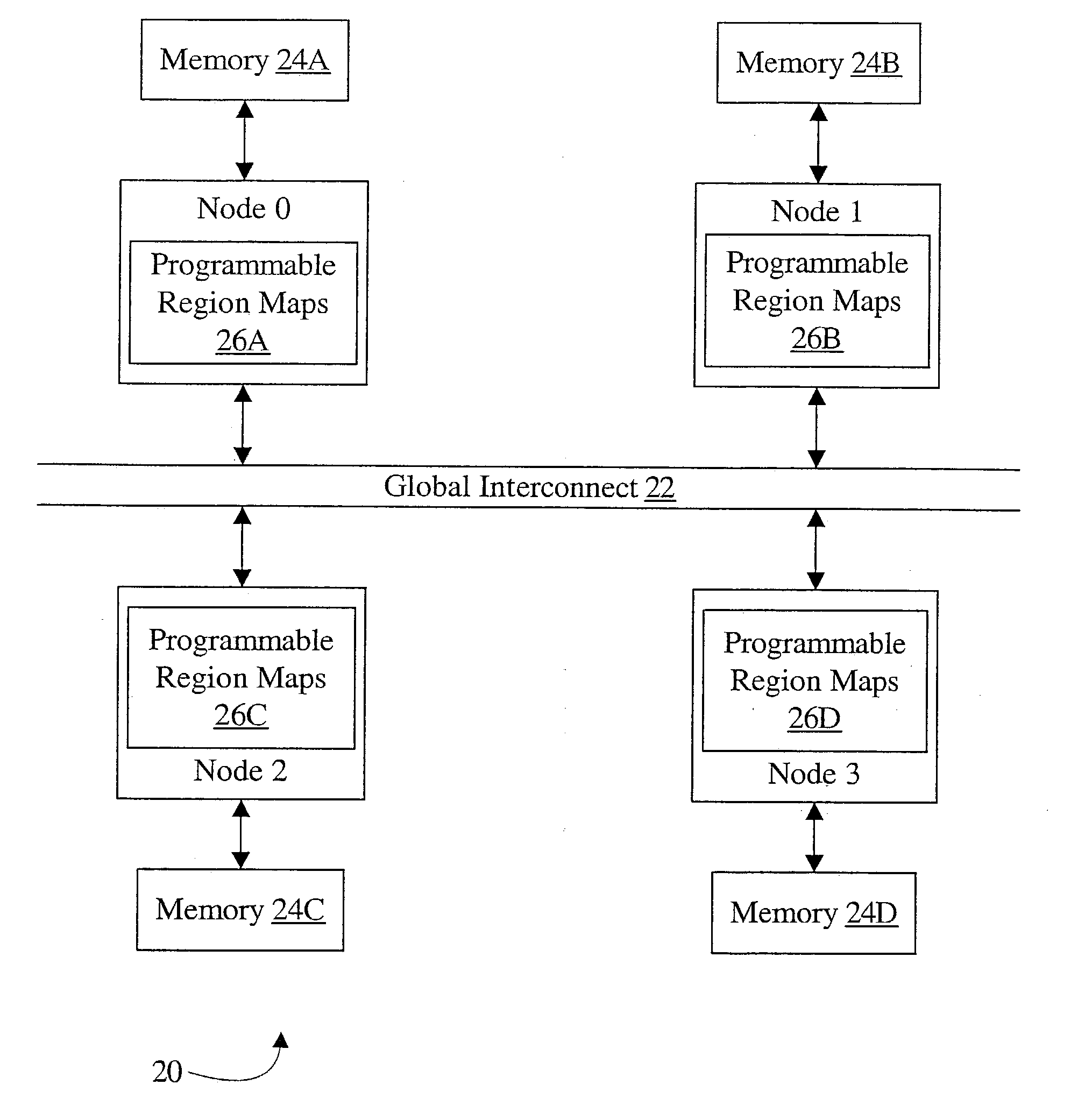
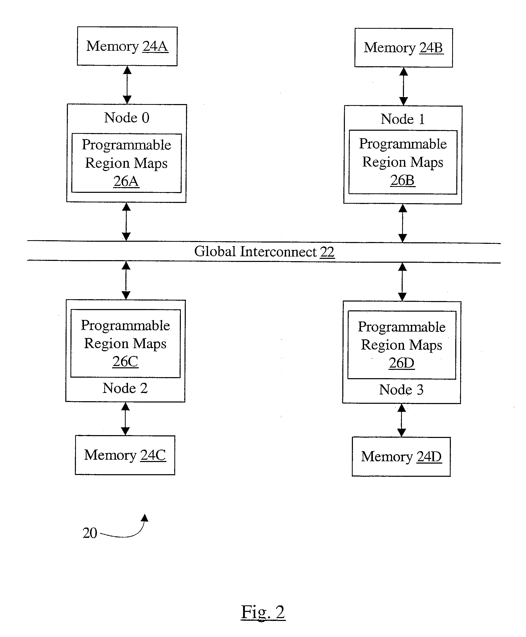
[0024] Turning now to FIG. 2, a block diagram of one embodiment of a system 20 including a plurality of nodes (node 0 through node 3) coupled to a global interconnect 22 is shown. In the illustrated embodiment, each node is coupled to a respective local memory 24A-24D. Each node includes a storage (26A-26D, respectively, in FIG. 2) that stores programmable region maps. The number of nodes in a given embodiment may vary, and may be more or fewer than the number of nodes shown in FIG. 2. Additionally, not all nodes may have local memory, in some embodiments.

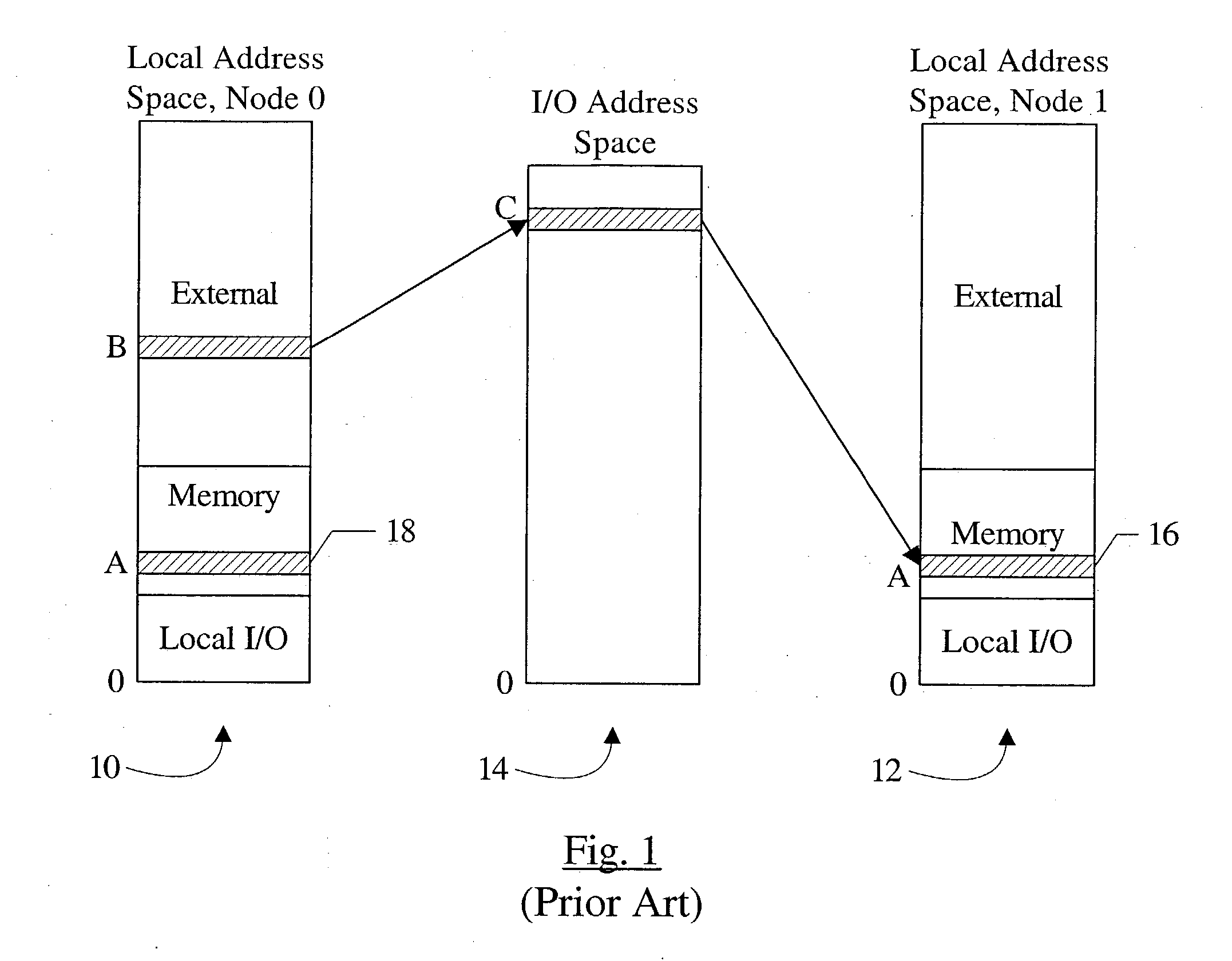
[0025] Each node may have its own local address space, used to address (or "refer to") resources within the node. Additionally, a global address space is employed for transactions on the global interconnect 22. The transactions on the global interconnect 22 may be used, for example, to communicate between the nodes 0 through 3.

[0026] Each node may have one or more regions in its local address space. Each region is assigned one or m...


PUM


Abstract

A node comprises at least one agent and an input / output (I / O) circuit coupled to an interconnect within the node. The I / O circuit is configured to communicate on a global interconnect to which one or more other nodes are coupled during use. Addresses transmitted on the interconnect are in a first local address space of the node, and addresses transmitted on the global interconnect are in a global address space. The first local address space includes at least a first region used to address at least a first resource of the node. The node is programmable, during use, to relocate the first region within the first local address space, whereby a same numerical value in the first local address space and a second local address space corresponding to one of the other nodes coupled to the global interconnect refers to the first resource in the node during use.

Description

[0001] This application claims benefit of priority to U.S. Provisional Patent Application Serial No. 60 / 380,740, filed May 15, 2002. The above application is incorporated herein by reference in its entirety.[0002] 1. Field of the Invention[0003] This invention is related to address spaces in multi-node systems and, more particularly, to mapping local and global addresses.[0004] 2. Description of the Related Art[0005] In many systems, multiple nodes are coupled together to form the system. Each node may comprise an integrated circuit, or multiple integrated circuits and / or other devices (e.g. input / output (I / O) devices and / or interfaces). Each node has a local address space used to address memory in the node or coupled to the node ("local memory"), as well as various I / O devices or interfaces in the node. Typically, the address spaces are relatively fixed (e.g. various regions within the address space are dedicated to local memory or I / O devices). There may be some amount of programm...

Claims


Application Information

Patent Timeline
Patent Type & Authority Applications(United States)
IPC IPC(8): G06F3/00G06F9/42G06F12/00G06F12/08
CPCG06F13/1684
Inventor MOLL, LAURENT R.KELLY, JAMES D.GULATI, MANUONER, KORAYROWLANDS, JOSEPH B.
Owner AVAGO TECH INT SALES PTE LTD
Learn More