
Saw cutting guide

a cutting guide and saw technology, applied in the direction of manufacturing tools, portable power driven saws, metal working devices, etc., can solve the problems of increasing the time required for a roofing installer, inconvenient control, and inordinate work, so as to achieve accurate and safe cutting of roofing materials. , the effect of easy control

Inactive Publication Date: 2004-02-26
FASNACHT SAMUEL +1
View PDF20 Cites 14 Cited by
  • Summary
  • Abstract
  • Description
  • Claims
  • Application Information

AI Technical Summary

Benefits of technology

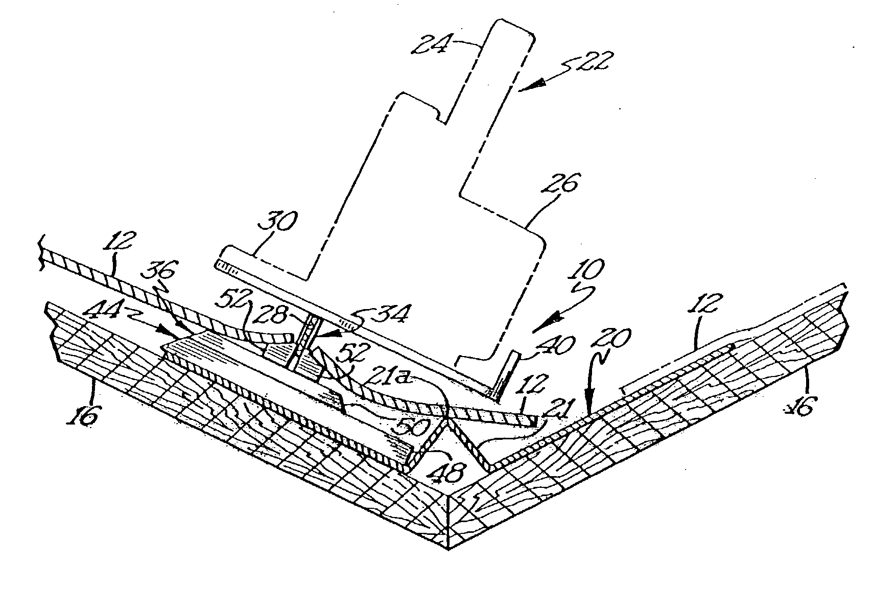
[0012] It is another object of the present invention to provide a cutting guide for use with a power saw that can be used to trim roofing materials at the gable end of a roof at a predetermined offset from the fascia boards and drip edge typically used to trim out the gable ends of roofs. Again, such a cutting guide must permit the neat and efficient cutting of the roofing materials avoiding damage to the fascia boards, drip edge, the sheathing of the roof itself, and any damage to the remaining roofing materials.
[0102] FIG. 16 comprises yet another embodiment of a blade 28 having a cutting edge that is inclined radially inwardly in the direction of rotation of the blade 28. This type of cutting edge 82 has a shearing action and will effectively slice roofing materials 12. While not as aggressive as a chisel type cutting edge 82 such as that illustrated in FIG. 15, this slicing action helps to prevent the formation of large quantities of swarf, and therefore prevents the buildup of swarf on the saw 22 and saw blade 28. FIG. 16a illustrates the cross section of the tooth 78 of the blade embodiment of FIG. 16.

Problems solved by technology

Unfortunately, given the nature of many roofing materials and especially standard asphalt shingles, the quickest and most flexible manner in which the shingles may be trimmed away from the center of the valley is by hand.
While a number of these improvements do increase the safety and possibly even the efficiency of cutting shingles at a predetermined offset from the valley by hand, the job still requires an inordinate amount of time and is still quite labor intensive.
However, use of a shear-like cutting device requires the roofing installer to measure and fit each shingle individually along an entire roof valley.
Given the large quantity of roof valleys typically present on a roof, the additional measuring and fitting steps may actually increase the amount of time necessary for a roofing installer to install shingles adjacent to a roof valley.

Method used


Image

  • Saw cutting guide
  • Saw cutting guide
  • Saw cutting guide

Examples


Embodiment Construction

[0105] A preferred embodiment of the present invention may be seen in FIGS. 19-22. The cutting guide 100 as shown in FIG. 19 comprises a saw 102 that is secured to a mounting plate 104 by a number of arcuate clamps 106. The arcuate clamps 106 apply a clamping force to the saw 102 by means of a wing nut 108 that is threaded onto a bolt 110 received through the mounting plate 104. The saw 102 may be a standard circular saw of the corded or cordless variety or may be formed integrally with the mounting plate 104 such that the cutting guide 100 will be a substantially unitary structure. In either case, the cutting guide 100 will function identically.

[0106] The mounting plate 104, and hence the saw 102, is supported upon a post 114. Unlike the post 34 described herein above, post 114 is purposefully misaligned with a blade 112 of the saw 102. The nature of the post's 114 misalignment with the blade 112 will be described in more detail hereinbelow. The upper end of the post 114 is securel...


PUM

PropertyMeasurementUnit
distanceaaaaaaaaaa
offset distanceaaaaaaaaaa
distancesaaaaaaaaaa

Abstract

The present invention discloses a cutting guide that permits the use of a power saw in trimming roofing materials in the installation of those roofing materials. The cutting guide may be constructed as an accessory or as a unitary roofing material cutting apparatus and generally comprises a mounting plate for coupling a power saw to the cutting guide, a post extending downwardly from the mounting plate in general alignment with a blade of the power saw, and a base that supports the power saw and cutting guide and which has at least one lateral edge that is arranged substantially parallel with the blade of the power saw at a predetermined offset distance therefrom. The cutting guide of the present invention may be readily configured to trim roofing materials such as shingles, membranes, shakes, or tiles in roof valleys, at ridges, and at the gable end of a roof.

Description

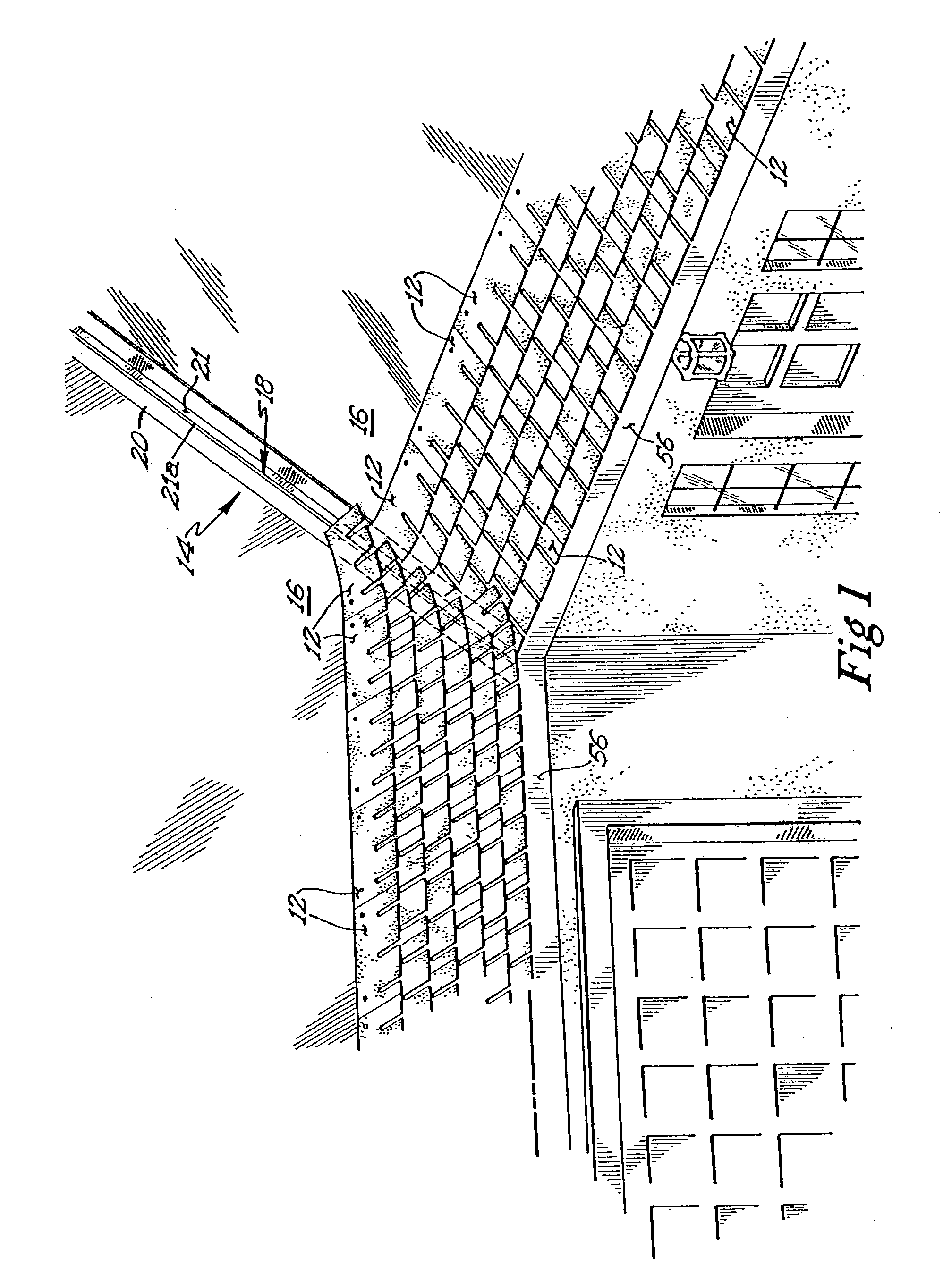
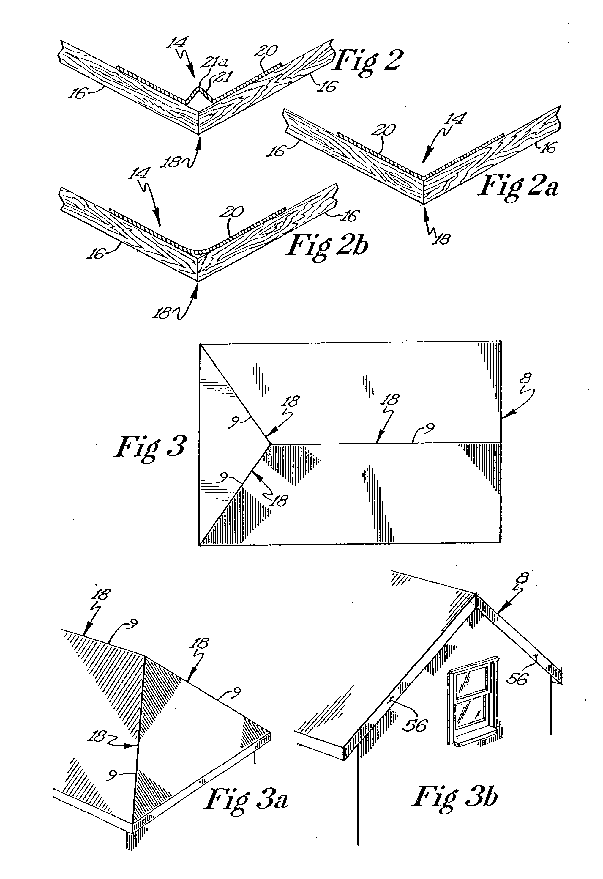
[0001] This application is a continuation in part of U.S. patent application Ser. No. 09 / 876,399 to Fasnacht et al. and filed on Jun. 7, 2001.[0002] The present invention relates to a mechanism for use in trimming or cutting roofing materials such as shingles, shakes, or membranes. More specifically, the present invention is drawn to a cutting guide that directs a cutting blade through a given roofing material at a predetermined offset from a given feature of a roof structure.[0003] Heretofore, one of the most time consuming and hence costly procedures in applying roofing materials such as shingles, shakes, tiles, and membranes to roofs has been the hand trimming of the roofing material at or near the valleys, ridges and gable ends of a roof. FIG. 1 illustrates a typical roof valley that is covered with shingles. A valley 14 is the concave juncture of two non-planar roof surfaces. Typically this juncture comprises a seam 18 formed in the sheathing material 16 used to form the roof. ...

Claims


Application Information

Patent Timeline
Patent Type & Authority Applications(United States)
IPC IPC(8): B23Q9/00B27B9/02B27B9/04
CPCB23Q9/0028B27B9/04B27B9/02Y10T83/762Y10T83/7647
Inventor FASNACHT, SAMUELOAS, MICHAEL
Owner FASNACHT SAMUEL
Learn More