Magnetic-based torque/speed sensor

a technology of torque/speed sensor and magnetic field, which is applied in the direction of speed/acceleration/shock measurement, measurement devices, instruments, etc., can solve the problems of increasing the weight of the battery, not being able to reliably and economically ascertain the torque transmitted in the chain wheel,

Inactive Publication Date: 2004-02-19
ABAS
View PDF10 Cites 18 Cited by
  • Summary
  • Abstract
  • Description
  • Claims
  • Application Information

AI Technical Summary

Benefits of technology

[0009] The need for a reliable measurement of torque in normal use has arisen as a means of gauging the effort expended by a cyclist in propelling the machine. It has been proposed to assist the rider of a pedal cycle by providing a motor drive by way of an electric motor powered by a battery carried by the cycle. The battery should be as compact and light as possible consistent with providing the drive energy required for reasonable periods. Raising battery capacity increases weight. To obtain the best use of battery life, it is desirable that the cycle should not be propelled solely by the battery energy for extended periods but that the battery energy should be called on to supplement the energy of the cyclist. The battery energy is only utilised provided the cyclist is providing at least a certain threshold propulsion energy. The energy supplied by the rider can be gauged by the torque exerted on the chain wheel driving the cycle chain. The present invention enables us to provide a solution to the torque measurement problem which can be then used in controlling the energisation of the electric motor.
[0010] Underlying the present invention is the concept of measuring torque in a gear or sprocket wheel, such as a bicycle chain wheel, by maintaining a magnetising source adjacent, but preferably not in contact with, the wheel as it rotates so that an arcuate zone of magnetisation is generated--this is a D.C. type of magnetisation in the terms discussed earlier--which zone is sensitive to torque in respect of a magnetic field or field component associated with it. This field or field component is detected by a magnetic field sensor. By having the source continuously in place the induced magnetisation in the wheel is refreshed or renewed on each rotation of the wheel. By this means subsequent events otherwise deleterious to a permanently magnetised transducer zone reliant solely on its own magnetisation can be overcome.

Problems solved by technology

Heretofore it has not been possible to reliably and economically ascertain the torque transmitted in a chain wheel while the cycle is being ridden in normal use, and particularly the torque exerted in the maximum torque phase.
Raising battery capacity increases weight.

Method used


Image

  • Magnetic-based torque/speed sensor
  • Magnetic-based torque/speed sensor
  • Magnetic-based torque/speed sensor

Examples


Embodiment Construction

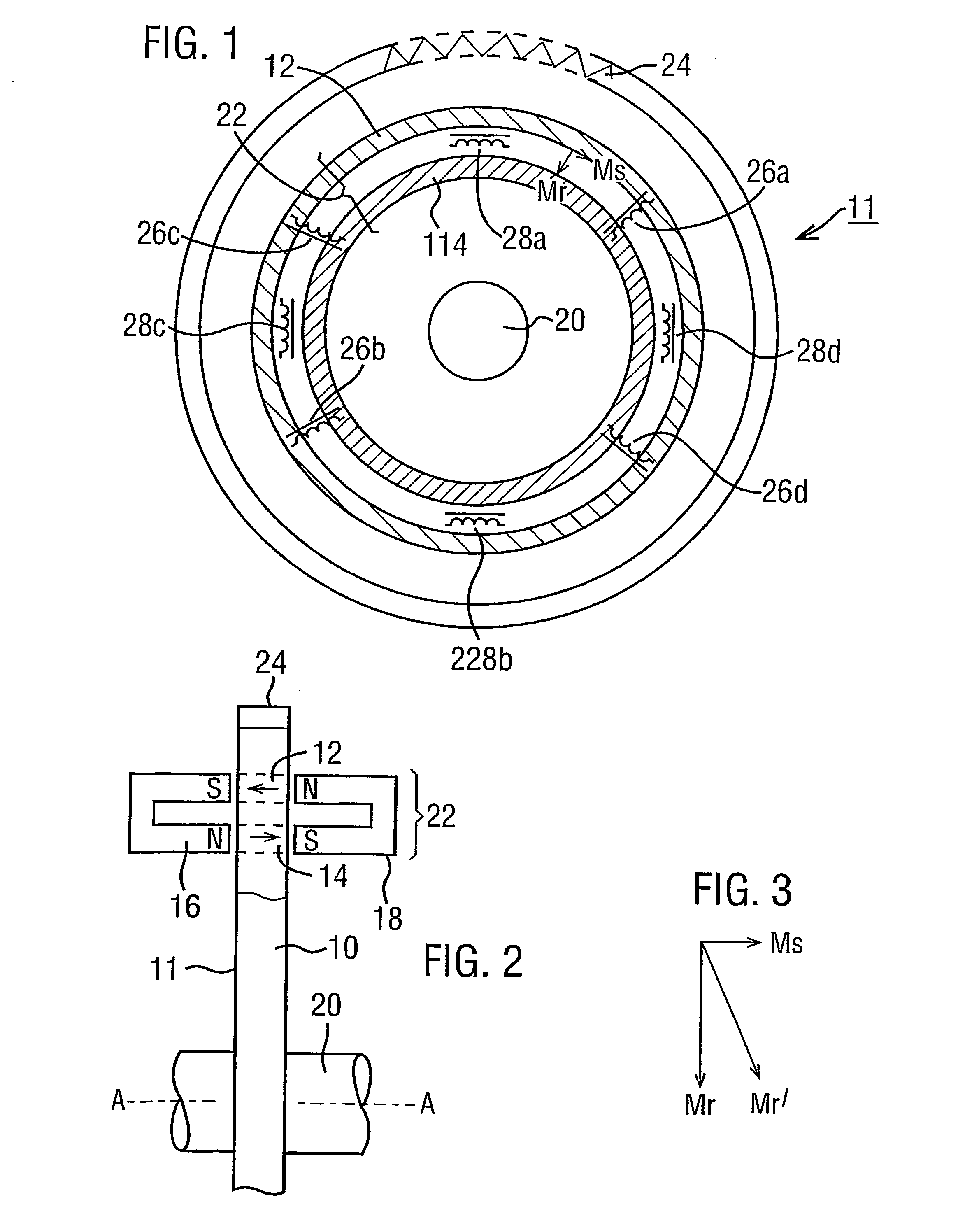
[0044] Start with the case that FIGS. 1 and 2 represent a chain wheel. The shaft 20 is coupled to the usual pair of opposed pedal cranks and the sprocket teeth communicate the rotational drive on the sprocket wheel 10 to the cycle chain. If the sprocket wheel is of magnetisable material that has been premagnetised as described with reference to FIGS. 1 and 2 for example, torque measurement can be made by appropriate placement of magnetic field sensor devices. It is assumed here that the cycle has an appropriate source of electrical energy for the torque sensing and signal processing circuitry. In the context of motor-assisted propulsion as discussed above, there will be an electrical battery source. Sensor devices and the accompanying electronics can be made in very compact, light form and can be placed adjacent the inside surface, i.e. inner, frame-side, surface, of the chain wheel so as to be out of the way of the cyclist. The magnets and sensor(s) can be mounted to the frame.

[004...


PUM


Abstract

Torque is measured in the chain wheel (50) of a pedal cycle by a non-contacting magnetic-based transducer. A magnetising source (70), a D.C. type of source such as a permanent magnet is positioned adjacent the chain wheel (50) to induce an arcuate magnetised zone (72) in the wheel (50) as it rotates. The zone emanates a torque-dependent magnetic-field component that is detectable by a sensor (74) that follows the source (70) in the direction of rotation. By having the magnetising source (70) continually in position the arcuate tranducer zone (72) is refreshed on each rotation of the chain wheel. The nature of the pulsating torque in the chain wheel due to the exertion of the rider and its relationship to the angle of the pedal cranks is discussed with a preference for positioning the source (70) and sensor (74) at positions of minimum and maximum exerted torque respectively. If the induced arcuate magnetisation is interrupted (76) pulses for measuring rotational speed are obtainable. The torque measurement is of general application to torque in sprocket wheels or gear wheels.

Description

[0001] This invention relates to a torque sensor arrangement in which torque is transmitted between two parts rotatable about an axis. The parts may be located at the same radius and mechanically coupled together, and more generally may be two axially spaced parts at the same or different radii. Of more immediate interest are parts located at different radii and radially coupled for the transmission of torque from one to the other. Of particular interest is where the parts lie essentially in a plane such as in a disc form of structure, for example a sprocket wheel.[0002] The invention also relates to a rotational speed sensor arrangement which incorporable as part of a torque sensor arrangement but which can be independently applied without being directly involved in torque transmission.BACKGROUND TO THE INVENTION[0003] A magnetically-based torque sensor arrangement for a disc-like structure is described in U.S. Pat. No. 4,697,460 (Sugiyama et al). This patent discloses an arrangeme...

Claims


Application Information

Patent Timeline
IPC IPC(8): G01L1/12G01P3/488G01L3/10G01L3/14G01P3/487
CPCG01L1/12G01P3/487G01L3/1435G01L3/14
Inventor MAY, LUTZ AXEL
Owner ABAS
Why Eureka
Try Eureka