Thermal activator for heat sensitive adhesive sheet and printer apparatus utilizing the thermal activator
- Summary
- Abstract
- Description
- Claims
- Application Information
AI Technical Summary
Problems solved by technology
Method used
Image
Examples
Embodiment Construction
[0077] A preferred mode for carrying out the present invention will now be described based on the drawings.
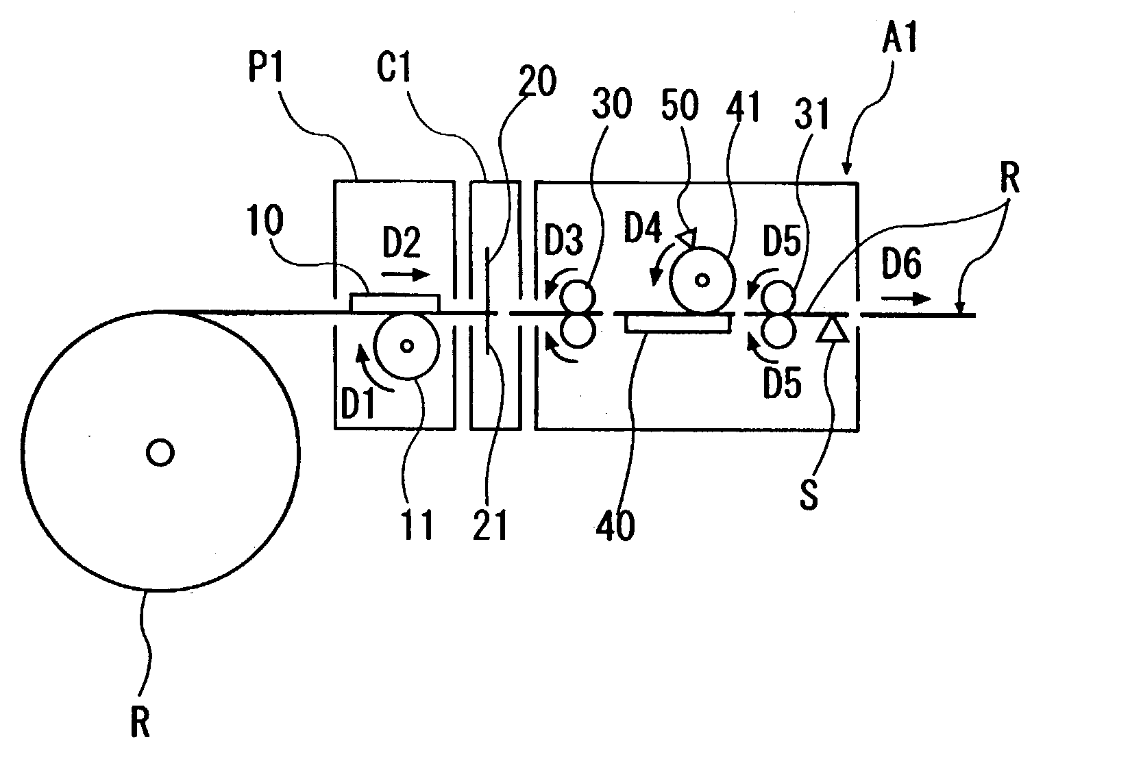
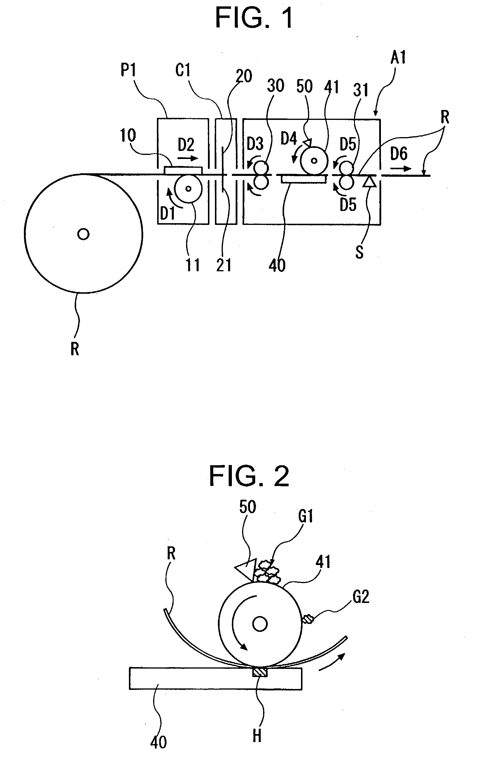
[0078] FIG. 1 is a schematic diagram showing a configuration of a thermal printer apparatus according to the present invention. In FIG. 1, reference sign P1 represents a thermal printer unit; reference sign C1 represents a cutter unit; reference sign A1 represents a thermal activation unit as a thermal activator; and reference sign R represents heat sensitive adhesive labels that are wound in the form of a roll.
[0079] The thermal printer unit P1 has a common configuration and has a thermal head 10 for printing, a platen roller 11 that is urged into contact with the thermal head 10 for printing, and a driving system that is not shown for rotating the platen roller 11 (e.g., an electric motor, a gear train, and the like).
[0080] The platen roller 11 is rotated in a direction D1 (clockwise) in FIG. 1 to pull out a heat sensitive adhesive label R, and the heat sensitive adhesive lab...
PUM
 Abstract
Description
Claims
Application Information
 - R&D
- Intellectual Property
- Life Sciences
- Materials
- Tech Scout
- Unparalleled Data Quality
- Higher Quality Content
- 60% Fewer Hallucinations
Browse by: Latest US Patents, China's latest patents, Technical Efficacy Thesaurus, Application Domain, Technology Topic, Popular Technical Reports.
© 2025 PatSnap. All rights reserved.Legal|Privacy policy|Modern Slavery Act Transparency Statement|Sitemap|About US| Contact US: help@patsnap.com


