
Automotive courtesy display

a technology for displaying vehicles and displaying messages, applied in the direction of vehicle components, signalling/lighting devices, optical signalling, etc., can solve the problems of inability to read the message by the drivers of other vehicles, the intended recipient of the message cannot visually make it out, and the conventional display system of automotive vehicle courtesy message display systems

Inactive Publication Date: 2003-12-11
YONG PETER
View PDF0 Cites 34 Cited by
  • Summary
  • Abstract
  • Description
  • Claims
  • Application Information

AI Technical Summary

Benefits of technology

[0011] Another object of the invention is to reduce road rage among drivers and thereby lower insurance premiums. The system is also very useful for educational purposes, especially to children and young drivers.
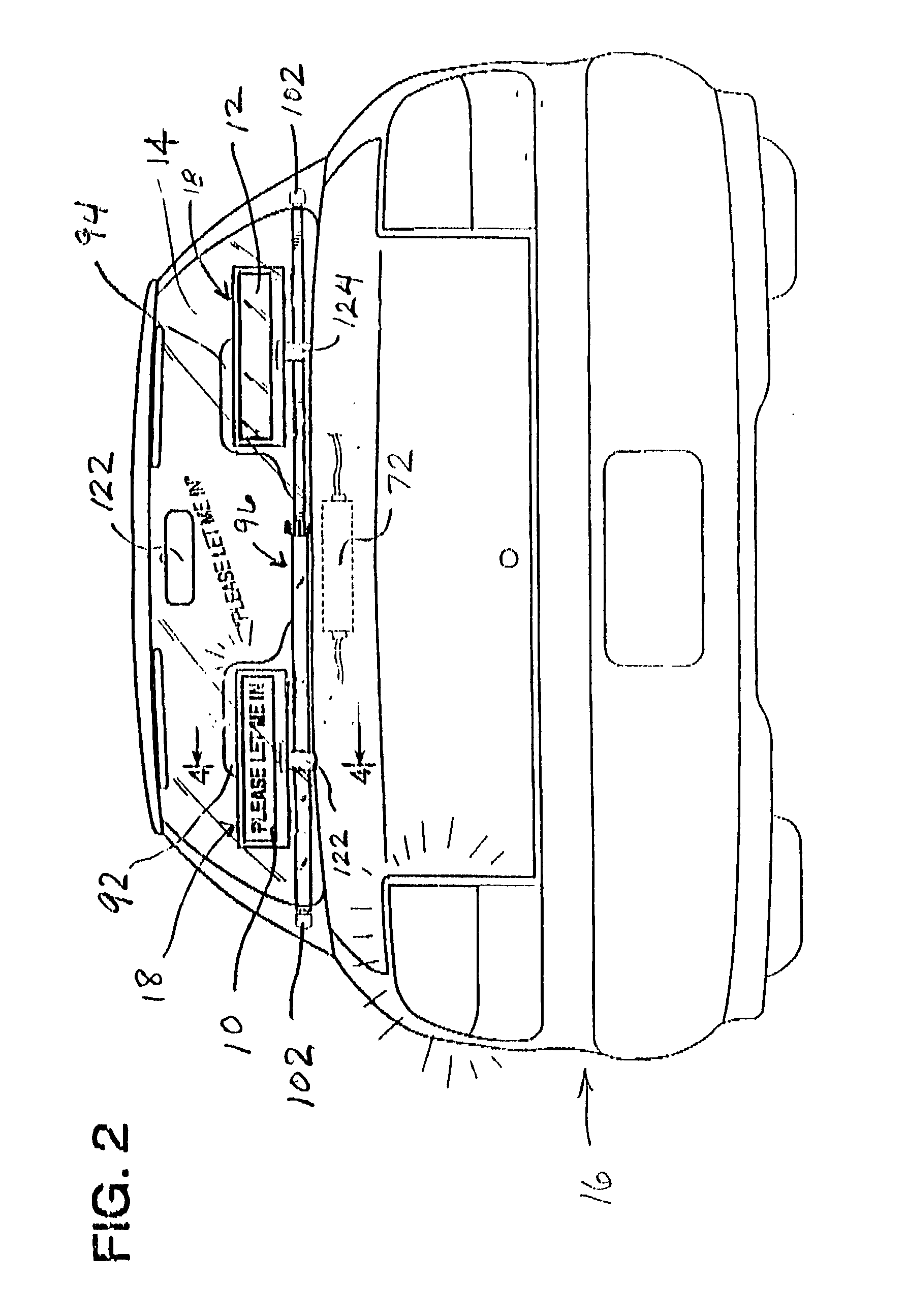
[0012] A further object of the present invention is to provide an automotive vehicle courtesy message display system that minimizes the visual obstruction through the rear windshield to the driver of the vehicle in which the message display system is installed. This objective may be achieved in a conventional passenger automobile by providing dual display units, one located behind each of the rear seat headrests of the vehicle. Virtually all conventional passenger vehicles are provided with front seats for the operator and at least one passenger, and a rear seat for additional passengers. The rear seat is typically configured to provide seating areas to the left and right of the center of the vehicle and to provide rear seat headrests at these locations. The headrests are actually provided for safety reasons to minimize whiplash that might occur in a collision.
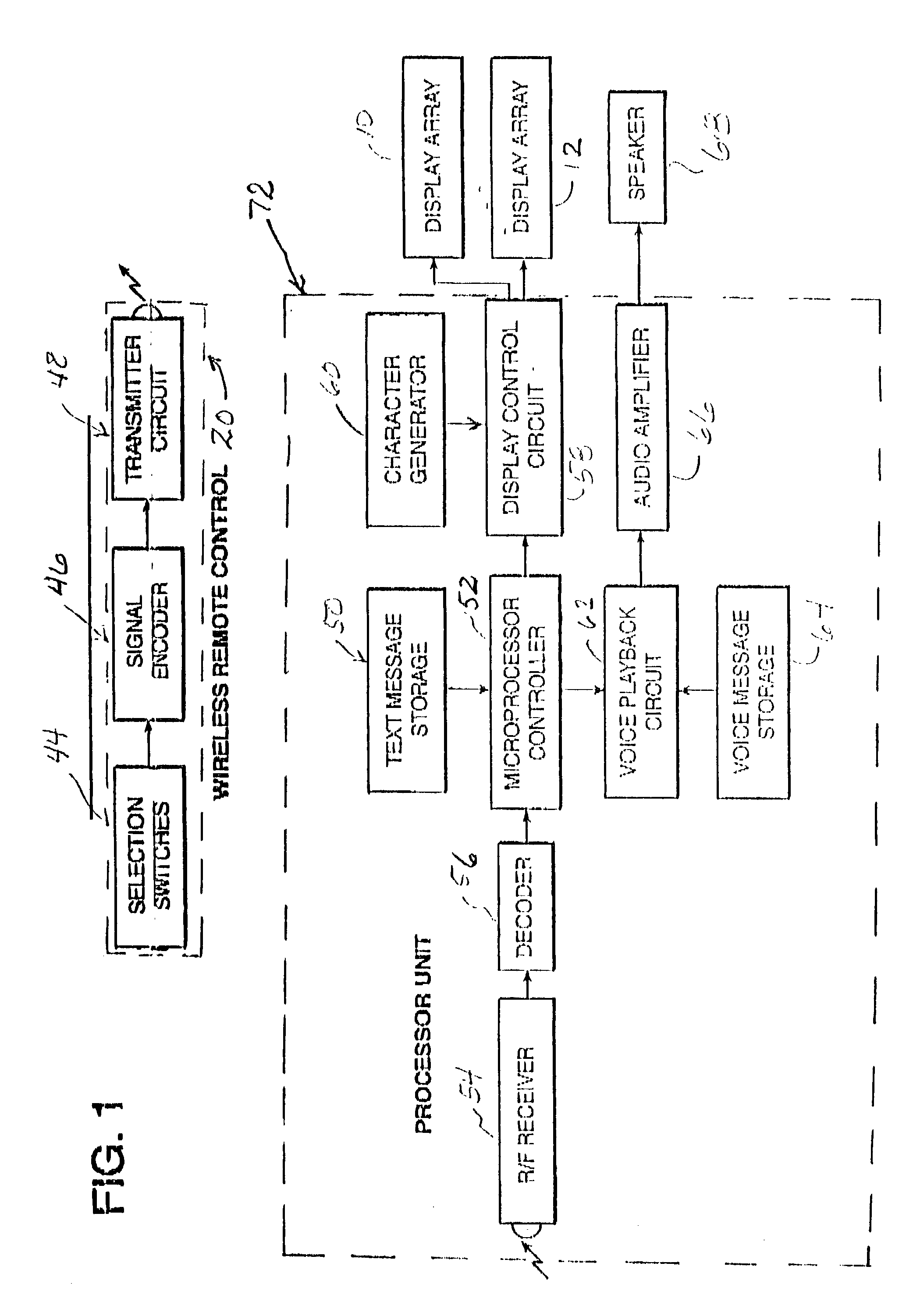
[0014] The visual obstruction presented by the display unit or units of the courtesy message display system of the invention is also significantly reduced by positioning only the display screen itself at a location above the level of the rear deck panel behind the rear vehicle seat. In conventional electronic courtesy message display systems the power unit for the display is located within the same housing as the actual LED elements that display the message. According to the present invention, however, the electronic drivers for the message display screen or screens are located within a separate casing that may be positioned at a location beneath the rear deck panel of the vehicle so as not to prevent a visual obstruction to the view of the driver through the rear window.
[0015] All of the operating electronics for the courtesy message display system of the invention are located within a housing that may be positioned out of the way and out of view of any occupant of the vehicle. More specifically, the housing containing most of the electronics for the message display system of the invention is preferably located directly beneath the generally horizontal deck that typically extends from the back of the rear seat headrests to the base of the rear windshield of most passenger vehicles. This area is typically accessible from the trunk of the vehicle. Thus, the largest bulk of the display unit of the invention is located in a concealed storage location so that it does not present a hazzard to persons in the vehicle in case of a collision. Also, the concealment of the major portion of the equipment prevents interference with the rear view vision of the driver of the vehicle.
[0016] A further feature of the invention is the very versatile mounting system which allows the display units to be installed in automotive vehicles having a variety of sizes and configurations. In this connection, the display screen units are mounted upon display supports that may moved along a mounting rail and secured thereto at appropriate positions on the mounting rail. Also, the mounting rail itself is constructed using members that are telescopically connected together so that the length of the mounting rail can be adjusted to the width of the vehicle at a location directly behind the rear passenger seat. Also, the outboard ends of the telescoping rail are provided with feet that are pivotally mounted to the ends of the rails so as to accommodate different surface configurations found at the interior walls near the rear of the passenger compartment of different vehicles.

Problems solved by technology

One significant shortcoming of conventional automotive vehicle courtesy message display systems is that they simply cannot be read by the drivers of other vehicles for whom they are intended due to interference from ambient light.
While displays of this type are readily visible to other nearby drivers in view of the display during hours of darkness, ambient daylight interferes with such displays to such an extent that the intended recipient of the message simply cannot visually make it out.
Accordingly, conventional displays of this type have limited utility, since they are really only useful during the hours of darkness.
It is during the daylight that conventional illuminated message display systems are ineffective.
Another difficulty with conventional message display systems is that the display is quite bulky.
If it is installed for observation through the rear windshield of a vehicle, it often significantly obstructs the rear view of the driver of the vehicle in which it is installed.
Thus, display of a courtesy message, though meant as a gesture that will facilitate the flow of traffic and thereby reduce accidents, actually becomes a hazard due to its vision limiting position in the vehicle.
A further disadvantage of conventional automotive courtesy message display systems is the lack of a suitable mounting system.
The positioning of the display in this manner not only presents a significant visual obstruction to the driver of the vehicle in which it is installed attempting to see through the rear windshield, but also is largely ineffective.
Available suction cup systems simply will not hold the display in position for any significant length of time.
A further disadvantage of conventional automotive vehicle courtesy message display systems is the distracting effect they have upon the driver operating them.
This requires the distraction of the visual attention of the driver from the traffic and the road ahead.

Method used


Image

  • Automotive courtesy display
  • Automotive courtesy display
  • Automotive courtesy display

Examples


Embodiment Construction

[0031] FIG. 1 illustrates diagrammatically the electronic components of an electronically operated visual courtesy message display system for an automotive vehicle constructed according to the present invention. Specifically, the display system of the invention includes at least one, and preferably dual, thin, elongated message display screens 10 and 12 that are positionable for viewing through the rear window 14 of an automotive vehicle 16 from the exterior thereof, as illustrated in FIGS. 2 and 3. As illustrated in FIG. 4, a display screen hood 18 is provided for shading each of the display screens 10 and 12.

[0032] FIG. 6 illustrates an operator panel or console 20 for mounting on the center 23 of a steering wheel 22 of the automotive vehicle 16. The operator console 20 includes an array of a plurality of individually actuable touch-sensitive selectors 24 through 42. Each of the selectors 24 through 42, upon actuation, provides a unique identifying electronic signal. The entire ar...


PUM


Abstract

An automotive vehicle courtesy message display system allows the driver of a automotive vehicle to visually display courtesy messages to the drivers of vehicles located to the rear. Such messages may be for an occasional urgent request to "cut in" for safe passage. The message display system provides the driver of the vehicle in which the visual display is installed with an audible feedback so that the vehicle driver can verify that the correct message has been selected, without visually distracting the driver's attention. The system includes three main components, namely a wireless control unit located on the vehicle operator's steering wheel, a processor unit containing most of the electronics of the system positioned in an unobtrusive location so as to avoid impairing the drivers view, and one or a pair of display screens which are typically located behind the rear seat headrests of an automotive passenger vehicle. A microprocessor controller withing the microprocessor unit selects a text message corresponding to the particular touch sensor depressed, and transmits it to an appropriate one the display screens. The audible announcement of the message selected by the touch sensor provides the operator with a positive feedback indicating selection of the correct message.

Description

[0001] 1. Field of the Invention[0002] The present invention is a system for electronically displaying courtesy messages by a driver within one automotive vehicle to drivers of other nearby automotive vehicles.[0003] 2. Description of the Prior Art[0004] Various automotive courtesy message display systems have been devised for allowing the operator of an automotive vehicle to display courtesy or informational messages to the operators of other nearby automotive vehicles. Such messages are useful for requesting an act of courtesy on the part of the operator of a nearby vehicle and for expressing graciousness toward the actions that have been taken by another automotive vehicle operator.[0005] Conventional devices of this type are often located on the outside of a vehicle, either upon the trunk or rear body structure of the vehicle. Alternatively, they may be located within the vehicle, but visible through a rear windshield. Conventional devices of this type are described, for example...

Claims


Application Information

Patent Timeline
IPC IPC(8): B60Q1/50
CPCB60Q1/503B60Q1/50B60Q1/5035B60Q1/549
Inventor YONG, PETER
Owner YONG PETER
Learn More