
Image printing using print quality enhancing ink

a printing medium and print quality technology, applied in printing and other directions, can solve the problems of difficult to achieve the desired color, ink is absorbed by the printing medium, and the person viewing the image experiences unpleasant impressions of different levels of gloss in different areas,

Inactive Publication Date: 2003-11-27
NEC CORP +1
View PDF1 Cites 28 Cited by
  • Summary
  • Abstract
  • Description
  • Claims
  • Application Information

AI Technical Summary

Benefits of technology

[0011] The present invention is also directed to a printing device for printing images by ejecting ink onto a printing medium, the printing device being capable of utilizing a first printing medium with relatively high gloss or a second printing medium with relatively low gloss. The printing device comprises: a print head configured to eject colored ink containing colorant, and quality enhancing ink for enhancing image quality of a print image; and an adjuster configured to adjust an ejection amount of the quality enhancing ink as a function of an ejection amount of the colored ink on the print image. The adjuster has: a first quality adjusting mode, applicable to the first printing medium, in which a first ejection amount of the quality enhancing ink in an image area where the colored ink is ejected on virtually all pixels is set lower than a second ejection amount of the quality enhancing ink in an image area where virtually no colored ink is ejected, thereby improving unevenness in gloss within the print image; and a second quality adjusting mode, applicable to the second printing medium, in which a third ejection amount of the quality enhancing ink in an image area where the colored ink is ejected on virtually all pixels is set higher than a fourth ejection amount of the quality enhancing ink in an image area where virtually no colored ink is ejected, thereby improving unevenness of coloring within the print image.
[0012] The present invention is further directed to a printing control device for generating print data from image data, the print data representing an ink ejection state at each pixel of a print image, the ink ejection state including an ejection amount of colored ink containing colorant and an ejection amount of quality enhancing ink for improving image quality of the print image. The printing control device comprises: ejection characteristic designation receiving means for receiving an ejection characteristic designation that specifies ejection characteristics of the quality enhancing ink; ejection characteristics modifying means for modifying the ejection amount of the quality enhancing ink on the basis of the received ejection characteristic designation; and print data generating means for generating print data representing the ink ejection state including the ejection amount of the colored ink and the modified ejection amount of the quality enhancing ink at each pixel of the print image.

Problems solved by technology

A resulting problem is that a person viewing the image experiences unpleasant impression of different levels of gloss in different areas of the same image.
When the image is printed on a printing medium of relatively low gloss, on the other hand, the ink tends to be absorbed by the printing medium.
As a result, less ink colorant remains on the surface of the printing medium, and areas which are supposed to be covered by the ink on the printing medium do not develop on the surface, making it difficult to attain the desired coloring.
The unevenness of coloring is especially noticeable in areas where large amounts of ink have been ejected, such as areas in which ink has been ejected on virtually all of the pixels.
When images of human figures are printed against a white background, for example, the unevenness of coloring will occur in the area of the human figures containing a greater amount of ink, causing graininess in the image.
When no enhancing ink is used, the colored ink ejected onto the human figure. area R3 is absorbed by the printing medium, resulting in unevenness of coloring.

Method used


Image

  • Image printing using print quality enhancing ink
  • Image printing using print quality enhancing ink
  • Image printing using print quality enhancing ink

Examples


second embodiment

[0123] C.

[0124] C1. General Structure of the Second Embodiment:

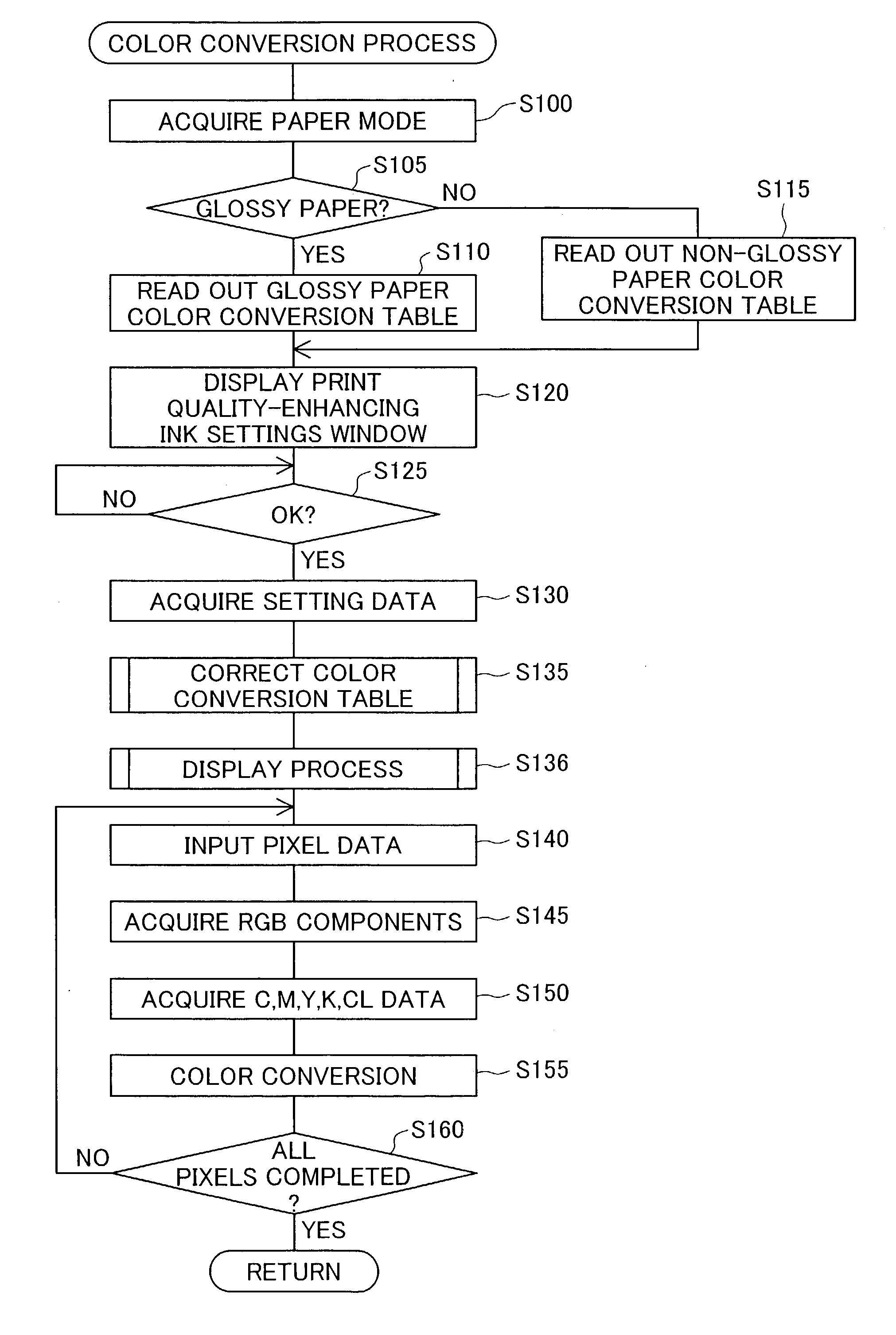
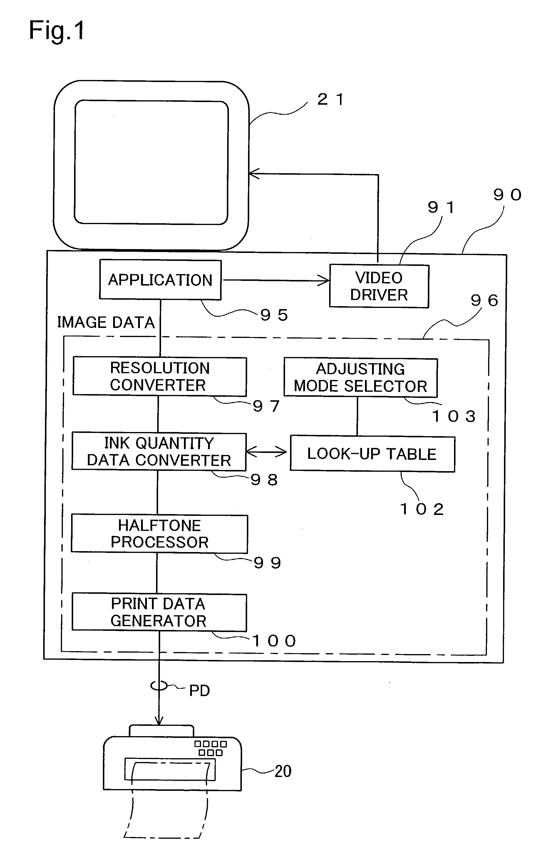
[0125] FIG. 20 is a block diagram illustrating the structure of the printing system in a second embodiment of the invention. The printer driver 96 in this printing system includes two color conversion tables 202a, 202b, a paper mode selector 203, and an ejection characteristic instruction receiver 204 in place of the look-up table 102 and the adjusting mode selector 103 in the system of the first embodiment (FIG. 1).

[0126] When printer 20 has a plurality of available paper modes, the user can select the paper mode to be used, using the paper mode selector 203. Where only one paper mode is available, the process performed by paper mode selector 203, or the paper mode selector 203 itself, may be omitted. In the second embodiment, one may select a first paper mode when using "glossy paper", and a second paper mode when using "non-glossy paper". The first and second paper modes correspond to the first and second adjusting mo...


PUM


Abstract

Image quality is improved by adjusting the ejection amount of quality enhancing ink based on the ejection amount of colored ink containing colorant. When a relatively high gross printing medium is used, the quality enhancing ink is ejected in an image area where virtually no colored ink is ejected, thereby improving unevenness in gloss within the print image. When a relatively low gross printing medium is used, on the other hand, the quality enhancing ink is ejected in an image area where the colored ink is ejected on virtually all pixels, thereby improving unevenness in color within the print image. The relationship between the ejection amounts of the quality enhancing ink and the colored ink may be modified by the user.

Description

[0001] 1. Field of the Invention[0002] The present invention relates to a printing device for printing images by ejecting a plurality of inks onto printing media.[0003] 2. Description of the Related Art[0004] In recent years, ink jet printers have come to enjoy widespread use as image printing devices. Users may select desired print media from among a variety of available types for use in ink jet printers. Such print media include, for example, "glossy" paper having relatively high gloss, "plain" paper having relatively low gloss, matte paper, and so on.[0005] The amount of ink that is ejected onto printing media is determined by the image data that is to be printed. Greater amounts of ink are ejected in areas of low brightness, and lower amounts of ink are ejected in areas of higher brightness.[0006] When an image is printed on a printing medium of relatively high gloss, the gloss tends to be more intense in areas where more ink has been ejected. For example, when images of human f...

Claims


Application Information

Patent Timeline
IPC IPC(8): B41J2/21
CPCB41J2/2114B41J2/17566
Inventor YAMAZAKI, SATOSHIYAMAMOTO, YUKO
Owner NEC CORP
Learn More