
Method and apparatus for friction stir welding

a technology of friction stir welding and friction welding, which is applied in the direction of soldering apparatus, manufacturing tools,auxillary welding devices, etc., can solve the problems of increasing the manufacturing cost of the finished assembly, increasing the cost of continuous support, and unable to provide adequate support for the weld joint, so as to achieve the effect of effectively supporting the weld joint and being easy to adap

Inactive Publication Date: 2003-10-30
THE BOEING CO
View PDF22 Cites 79 Cited by
  • Summary
  • Abstract
  • Description
  • Claims
  • Application Information

AI Technical Summary

Benefits of technology

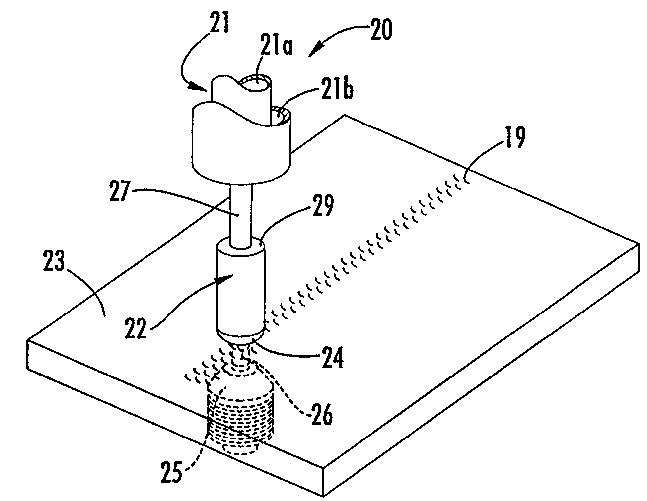
[0022] Thus, there has been provided a friction stir welding tool, apparatus and associated method of manufacture for forming weld joints by friction stir welding large workpieces or workpieces having curvilinear geometries. The tool is capable of effectively supporting a weld joint and constraining the plasticized material within the weld joint during friction stir welding. The tool can easily be adapted to varying workpiece geometries and sizes. In addition, the tool allows for friction stir welding workpieces having different material properties.

Problems solved by technology

When friction stir welding large workpieces or workpieces having curvilinear geometries, providing adequate support to the weld joint becomes problematic because the amount of support material necessary and / or the curvilinear geometry makes it more difficult and expensive to provide a continuous support surface.
However, weight restrictions and / or design parameters often require a finished assembly having a smooth interior surface.
As such, the tooling must be removed, for example, by machining, which is time consuming and labor intensive and increases the manufacturing cost of the finished assembly.
Another problem that has been encountered with friction stir welding occurs when joining workpieces formed of different materials having different material properties, such as solidus temperature, hardness, and / or thermal conductivity.
The different material properties can require that the friction stir welding tool be rotated within each workpiece at different rotational speeds and / or have different rates of tool advance through the workpieces, which can complicate the friction stir welding process and can limit the types of materials that can be joined.
For example, when friction stir welding workpieces with different solidus temperatures, the friction stir welding tool will plasticize the workpiece with the lower solidus temperature first, such that the workpiece with the higher solidus temperature may not be sufficiently plasticized to be mixed with the other workpiece, as is necessary to form a strong weld joint.

Method used


Image

  • Method and apparatus for friction stir welding
  • Method and apparatus for friction stir welding
  • Method and apparatus for friction stir welding

Examples


Embodiment Construction

Cross Reference to Related Applications

[0001] This application claims the benefit of U.S. Provisional Application No. 60 / 376,758, filed April 29, 2002.

Background of Invention

[0002] BACKGROUND OF THE INVENTION

[0003] Field of the invention The present invention relates to friction welding and, more specifically, to backing up a weld joint during friction stir welding.

[0004] Description of Related Art

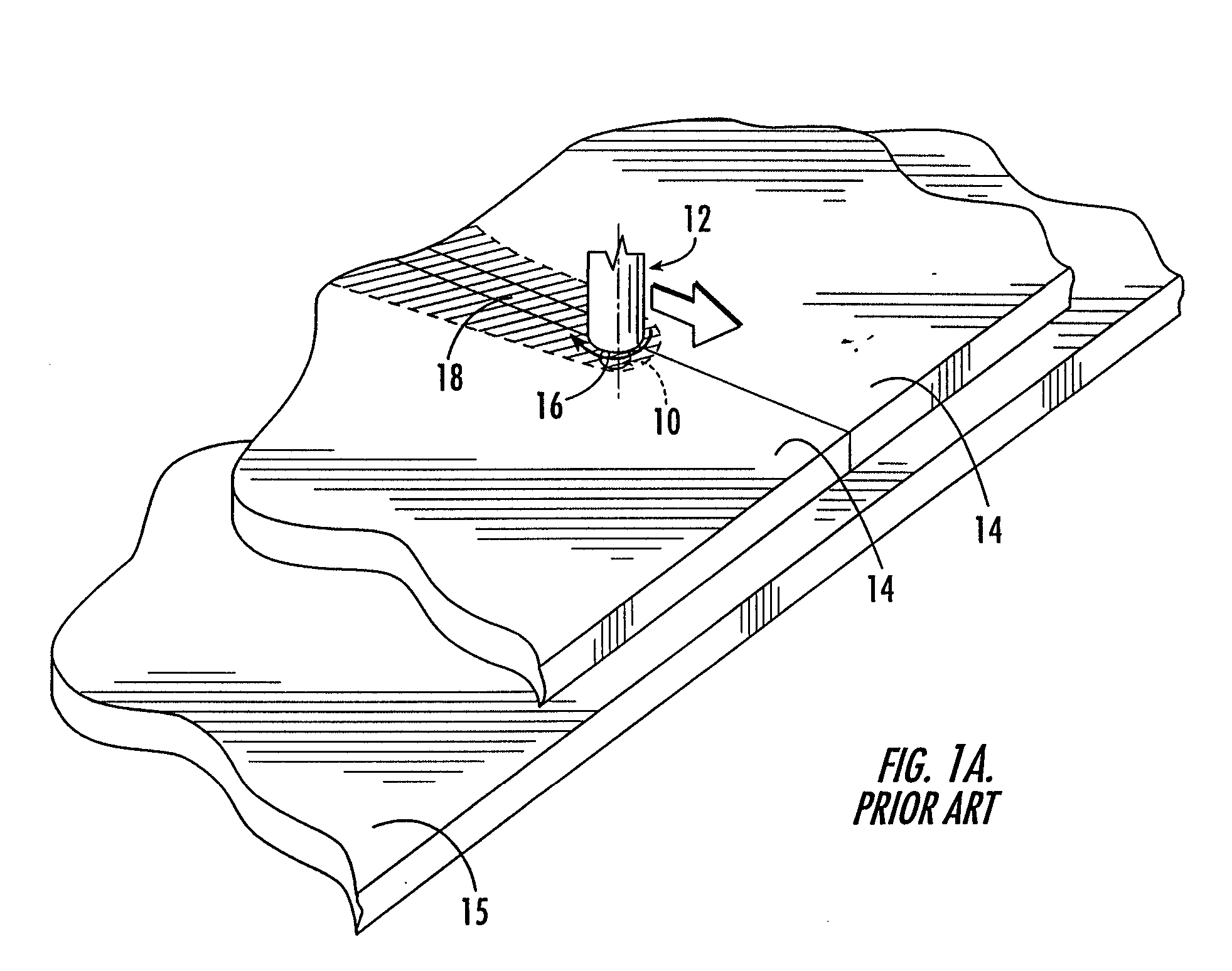
[0005] Friction stir welding is a relatively new process using a rotating tool, which includes a threaded pin or probe attached to a concave shoulder, to join in a solid state two workpieces or to repair cracks in a single workpiece. At present, the process is applied almost exclusively in straight-line welds. For example, such a process is described in U.S. Patent No. 5,460,317 to Thomas et al., the contents of which are incorporated herein by reference. As shown in Figure 1A, during friction stir welding, the probe 10 of the rotating tool 12 is plunged into a workpieceor between two work...


PUM

PropertyMeasurementUnit
thicknessaaaaaaaaaa
angular velocityaaaaaaaaaa
melting temperaturesaaaaaaaaaa

Abstract

Abstract of the Disclosure The present invention provides a tool for forming a friction stir weld joint in a workpiece. According to one embodiment, the tool includes a rotatable pin having first and second ends and defining a stirring portion therebetween structured to frictionally engage the workpiece so as to at least partially form the friction stir weld joint. The tool includes a rotatable first shoulder defining an aperture therethrough structured to slidably receive the first end of the pin. The tool also includes a second shoulder defining an aperture structured to receive the second end of the pin such that the pin extends between the first and second shoulders and such that the second shoulder is in rotatable communication with the pin. The first shoulder is structured to rotate independently of the pin and the second shoulder.

Description

Detailed Description of the InventionCross Reference to Related Applications[0001] This application claims the benefit of U.S. Provisional Application No. 60 / 376,758, filed April 29, 2002.Background of Invention[0002] BACKGROUND OF THE INVENTION[0003] Field of the invention The present invention relates to friction welding and, more specifically, to backing up a weld joint during friction stir welding.[0004] Description of Related Art[0005] Friction stir welding is a relatively new process using a rotating tool, which includes a threaded pin or probe attached to a concave shoulder, to join in a solid state two workpieces or to repair cracks in a single workpiece. At present, the process is applied almost exclusively in straight-line welds. For example, such a process is described in U.S. Patent No. 5,460,317 to Thomas et al., the contents of which are incorporated herein by reference. As shown in Figure 1A, during friction stir welding, the probe 10 of the rotating tool 12 is plunge...

Claims


Application Information

Patent Timeline
Patent Type & Authority Applications(United States)
IPC IPC(8): B23K20/12B23K103/10B23K103/14
CPCB23K20/122Y10T428/12493B23K20/1255B23K20/125B23K20/12
Inventor WALDRON, DOUGLAS J.MIRYEKTA, RAYMONDMCTERNAN, KEITH
Owner THE BOEING CO
Learn More