Optical heterodyne detection in optical cavity ringdown spectroscopy
a technology of optical cavity and ringdown spectroscopy, which is applied in the direction of spectrum investigation, color/spectral properties measurement, lasers, etc., can solve the problems of large optical loss in the system, inability to detect at greater sensitivities, and inability to meet the requirements of many applications
- Summary
- Abstract
- Description
- Claims
- Application Information
AI Technical Summary
Benefits of technology
Problems solved by technology
Method used
Image
Examples
first embodiment
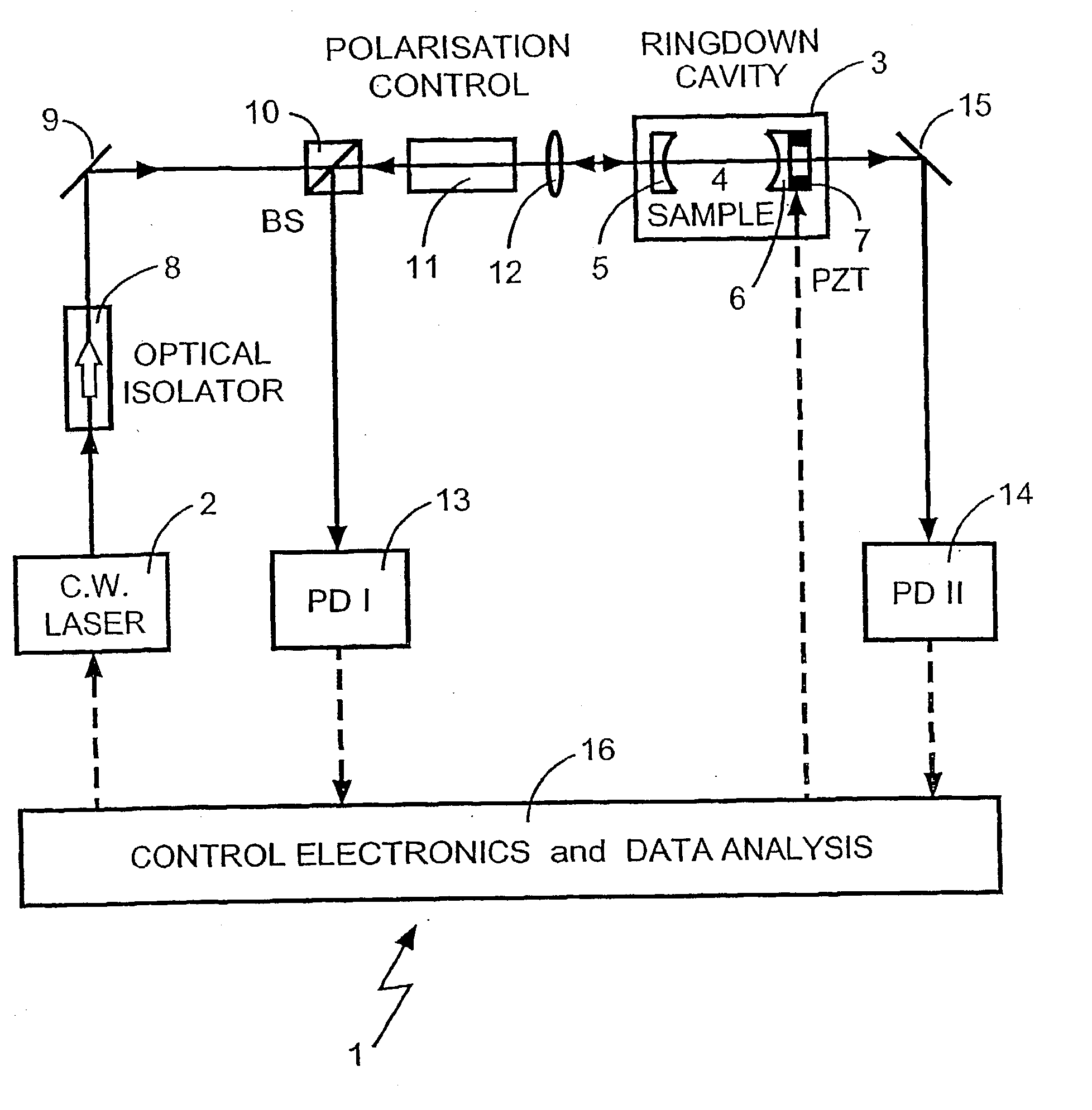
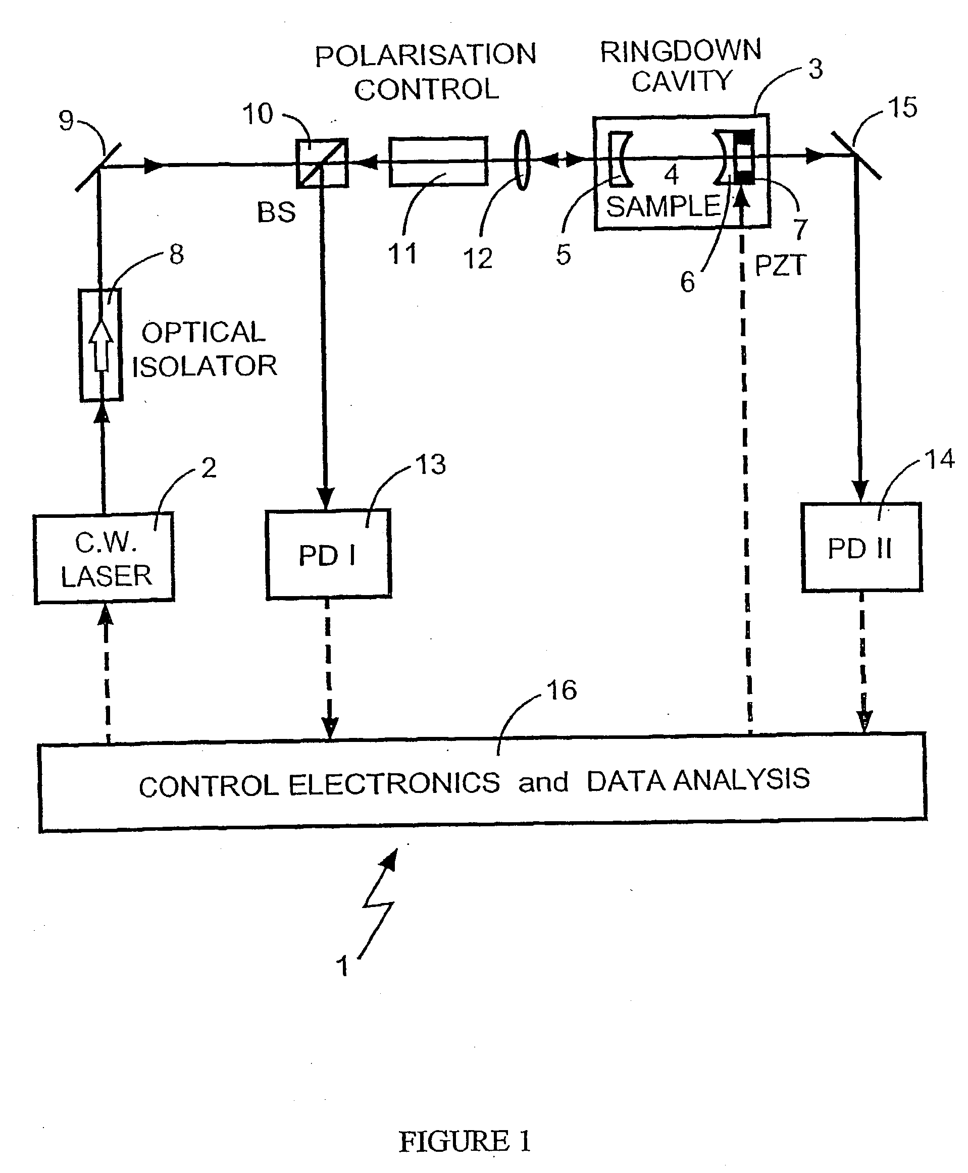
[0135] FIG. 5 shows an alternative embodiment to that shown in FIG. 1. Similar apparatus features are given the same reference numerals. This apparatus differs from that shown in FIG. 1 by the use of a single photodetector 17 and the fact that either of the mirrors 5, 6 can be moved (although in this drawing only mirror 6 is shown as being capable of being moved). Beam splitter 10, polarisation control unit 11 and photodetector 13 which appear in FIG. 1 are not needed in this embodiment. Additional beam splitter 18 directs a portion of emitted laser radiation along a second optical path to a second beam splitter 19, where it is combined with ringdown radiation emerging from the mirror 6 and forwarded by reflector 15 to the photodetector 17. For applications using high output energy lasers this embodiment is a good choice due to its simplicity. However this embodiment is less desirable than that of the first embodiment shown in FIG. 1 owing to less efficient use of available laser ou...
example 1
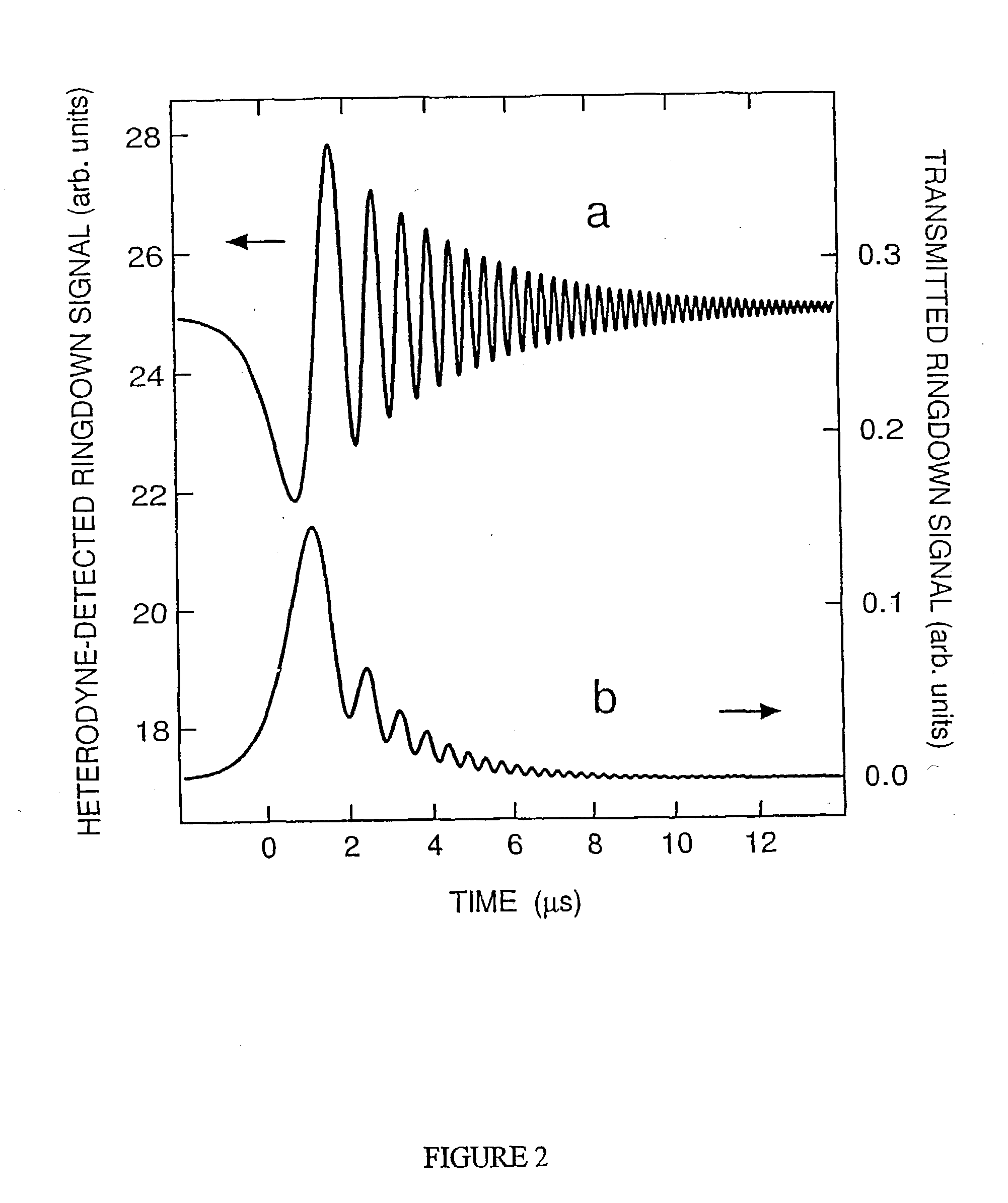
[0136] The rovibrational optical absorption band of carbon dioxide gas (CO.sub.2) at .about.1.53 .mu.m was examined spectroscopically using the optical-heterodyne detection continuous wave CRDS method of the present invention with a rapidly swept optical cavity and using the apparatus shown in FIG. 1. The apparatus used included a cw TDL tunable diode laser (New Focus model 6262 / 6200; .about.5 mW single-mode output; tunable over 1.50-1.59 .mu.m with .about.1-MHz optical bandwidth), a piezoelectrically controlled ringdown optical cavity, two amplified photodetectors 13 and 14 (InGaAs; 125-MHz bandwidth), a digital oscilloscope (Tektronix TDS3054; 500-MHz bandwidth), and control electronics with IEEE-488 computer interface. The TDL beam traversed an optical isolator (-80 dB) and was mode-matched to the ringdown cavity by a lens of 50-cm focal-length. A polarisation control unit (a 45.degree. Faraday rotator which also augmented optical isolation) enabled a polarising beam splitter (PB...
example 2
[0157] We now consider a second detailed example to illustrate the application of multi-wavelength optical heterodyne cw-CRDS by means of apparatus of the form depicted in FIGS. 11, 12 and 15. The example concerns simultaneous detection of the gas-phase species carbon monoxide (CO) and carbon dioxide (CO.sub.2). Measurement of the CO / CO.sub.2 ratio in exhaled air can be used to diagnose certain medical conditions. Likewise, the ratio of these two species is a key indicator of combustion processes in industry and the environment, where incomplete combustion or inefficient conversion of hydrocarbon fiels results in higher relative concentration of CO. Spectroscopic, laser-based detection of the CO / CO.sub.2 ratio in combustion effluent streams (e.g., industrial smokestacks) offers the prospect of real-time combustion process control and / or environmental monitoring of air quality. For instance, this has already been recognised and implemented in the steel industry, where a tunable mid-i...
PUM
 Abstract
Description
Claims
Application Information
 - R&D
- Intellectual Property
- Life Sciences
- Materials
- Tech Scout
- Unparalleled Data Quality
- Higher Quality Content
- 60% Fewer Hallucinations
Browse by: Latest US Patents, China's latest patents, Technical Efficacy Thesaurus, Application Domain, Technology Topic, Popular Technical Reports.
© 2025 PatSnap. All rights reserved.Legal|Privacy policy|Modern Slavery Act Transparency Statement|Sitemap|About US| Contact US: help@patsnap.com


