Hydrodynamic brake
a brake and hydraulic technology, applied in the direction of rotary clutches, fluid couplings, couplings, etc., can solve the problems of complicated construction, unnecessarily high fuel consumption of vehicles having retarders, and the inability to completely negate the brake action
- Summary
- Abstract
- Description
- Claims
- Application Information
AI Technical Summary
Benefits of technology
Problems solved by technology
Method used
Image
Examples
Embodiment Construction
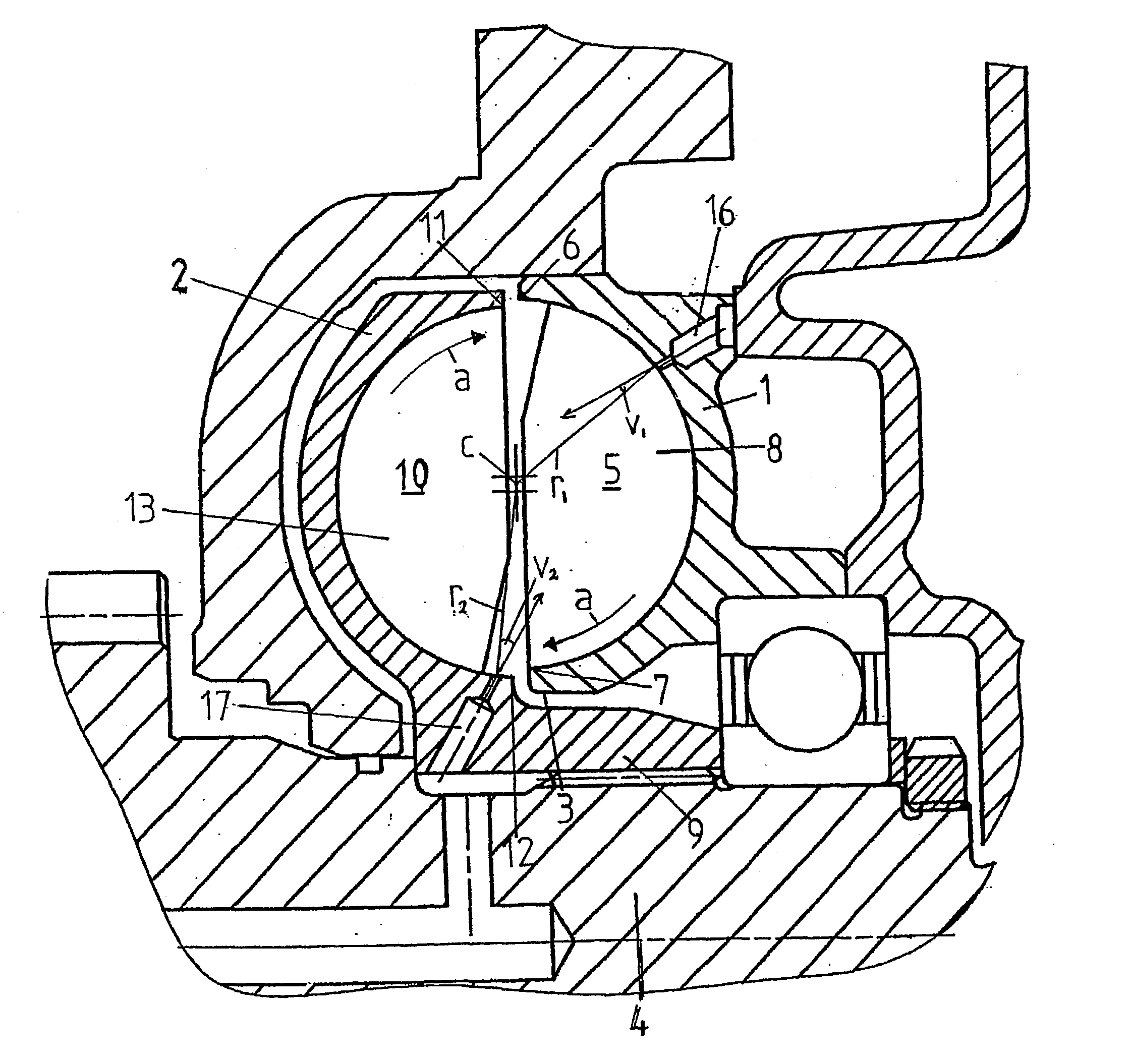
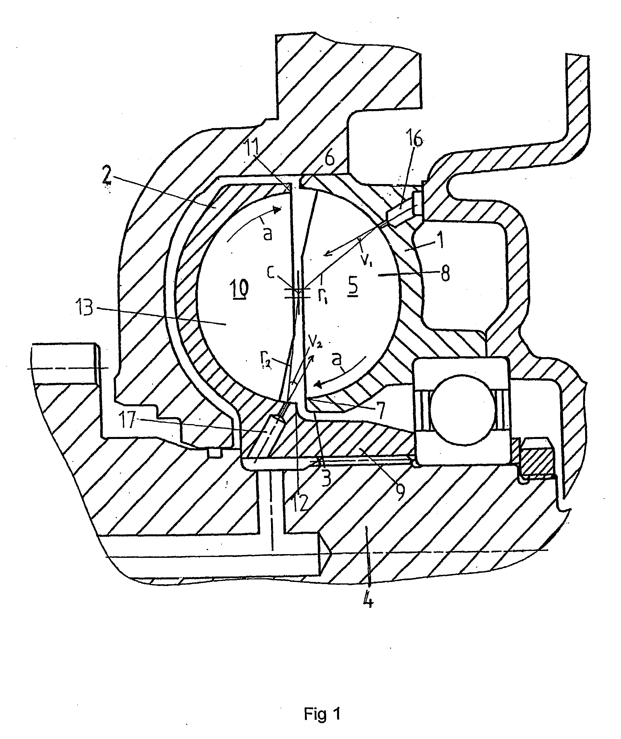
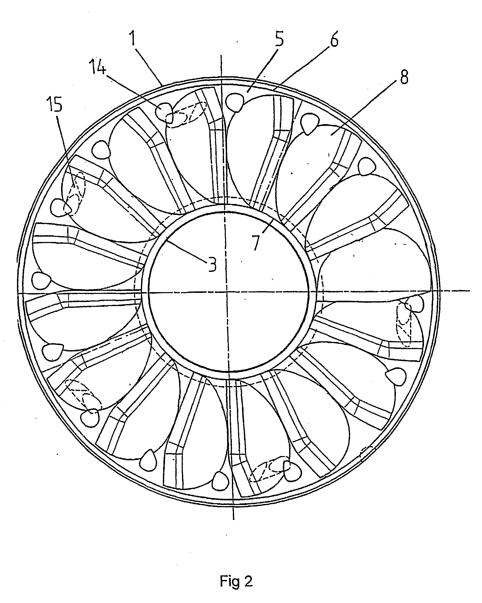
[0014] FIG. 1 shows a cross section through a portion of a hydrodynamic brake in form of a retarder of a motor driven vehicle. The retarder comprises a stator 1 and a rotor 2. The stator 1, which is shown separately in FIG. 2, comprises a body having an inner radial surface 3, which defines a circular opening. A rotatable shaft 4 is arranged to extend through the circular opening of the stator 1. The rotatable shaft 4 is, via a transmission device, in connection with a driving shaft of the vehicle. The stator 1 is fixedly provided in the vehicle in a suitable way. The body of the stator 1 comprises an annular recess 5, which in the mounted state of the retarder, extends around the rotatable shaft 4. The annular recess 5 is restricted in a radial direction outwards by an outer edge 6 and in a radial direction inwards by an inner edge 7. A number of vanes 8 are provided with uniform intervals along the circular extension of the annular recess 5. The vanes 8 have a substantially radial...
PUM
 Abstract
Description
Claims
Application Information
 - R&D
- Intellectual Property
- Life Sciences
- Materials
- Tech Scout
- Unparalleled Data Quality
- Higher Quality Content
- 60% Fewer Hallucinations
Browse by: Latest US Patents, China's latest patents, Technical Efficacy Thesaurus, Application Domain, Technology Topic, Popular Technical Reports.
© 2025 PatSnap. All rights reserved.Legal|Privacy policy|Modern Slavery Act Transparency Statement|Sitemap|About US| Contact US: help@patsnap.com


