
Brush support jig used in mounting a brush assembly of a rotary electric machine, and method of mounting the brush assembly using the brush support jig

Inactive Publication Date: 2003-08-28
DENSO CORP
View PDF5 Cites 13 Cited by
  • Summary
  • Abstract
  • Description
  • Claims
  • Application Information

AI Technical Summary

Benefits of technology

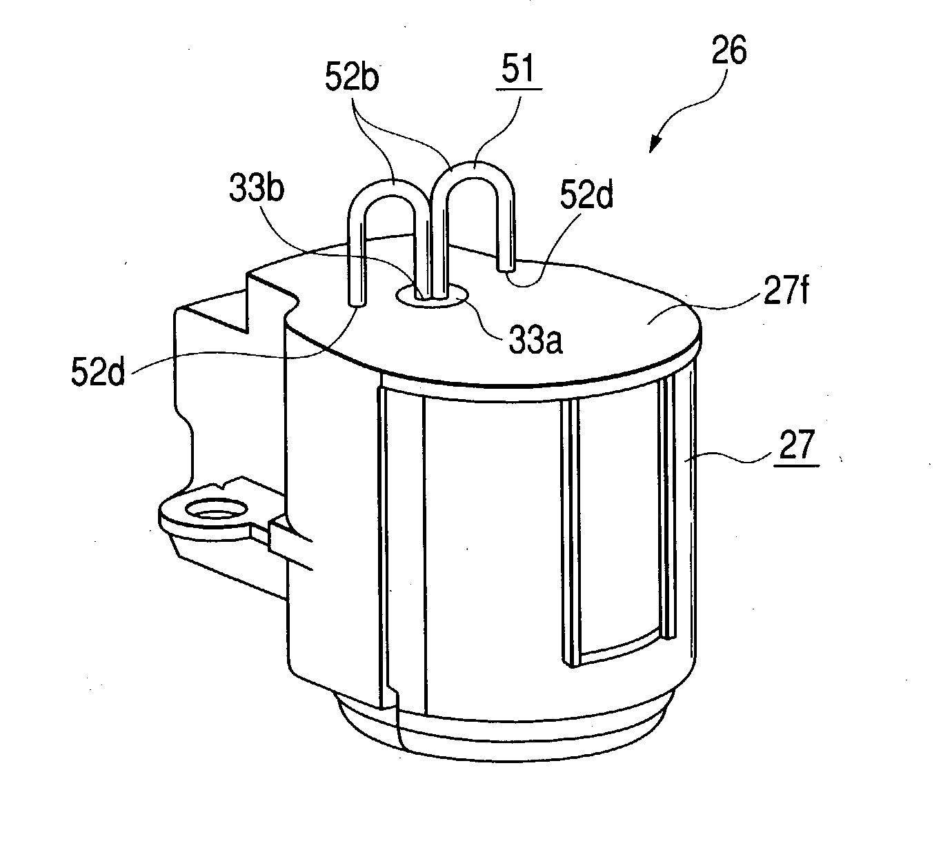
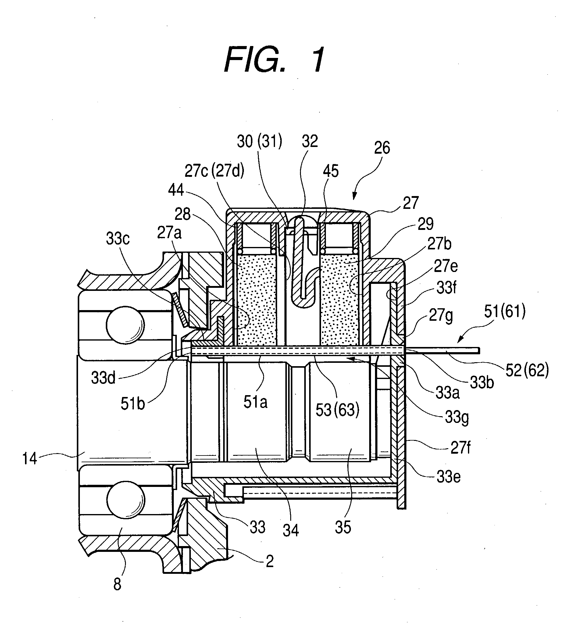
[0013] To achieve the first of the above objectives, according to a first aspect, the invention provides a brush support jig to be utilized when mounting a brush assembly of a rotary electric machine, the brush assembly including brushes which are in sliding contact with the outer peripheries of slip rings which are mounted on the shaft of the rotary electric machine, a brush holder for supporting the brushes with respect to the slip rings, and a slip ring cover which, together with the brush holder, surrounds the outer peripheries of the slip rings, with the brush support jig serving to prevent the brushes from flying out of the brush holder during mounting of the brush assembly, wherein the brush support jig has at least a face thereof, disposed opposite the slip rings, which is formed of a material that has a lower degree of hardness than the slip rings.
[0022] According to another aspect, a brush support jig according to the present invention is formed with a limiter portion which limits the extent of insertion of the brush support jig into the brush assembly. Hence, the brush support jig can be accurately inserted into the brush assembly. Furthermore, even if an operator should attempt to insert the brush support jig into the brush assembly to a greater extent than is actually required, this-will not result in damage to the brush holder in the brush assembly, or to the slip ring cover, or to the brush support jig itself.

Problems solved by technology

If there is a defect such as a surface scratch in the slip rings, then this can cause abnormal noise to be generated and can result in shortening of the operating life of the brushes.
Thus, the spacing between the slip rings and brush support jig must be relatively large, and hence the overall size of the brush assembly becomes large.
For that reason, such a configuration is not suited to the present-day requirements for greater compactness.
For that reason, the brush assembly becomes large in size, so that the present-day requirements for greater compactness cannot be satisfied by such an arrangement.
However due to manufacturing deviations in the shapes of components such as the slip ring cover, the rubber seal may not be pressed evenly around the rim of the slip ring cover, so that an effective seal cannot be ensured.
Moreover, due to changes in elasticity which will occur in the rubber seal, the cross-sectional area of a ventilation path which includes the rubber seal may be reduced, so that cooling ventilation of the areas of sliding contact between the slip rings and brushes may become insufficient.
It thereby becomes unnecessary to provide any other means of supporting the brush support jig.
It also becomes unnecessary to form holes in the brushes.

Method used


Image

  • Brush support jig used in mounting a brush assembly of a rotary electric machine, and method of mounting the brush assembly using the brush support jig
  • Brush support jig used in mounting a brush assembly of a rotary electric machine, and method of mounting the brush assembly using the brush support jig
  • Brush support jig used in mounting a brush assembly of a rotary electric machine, and method of mounting the brush assembly using the brush support jig

Examples


first embodiment

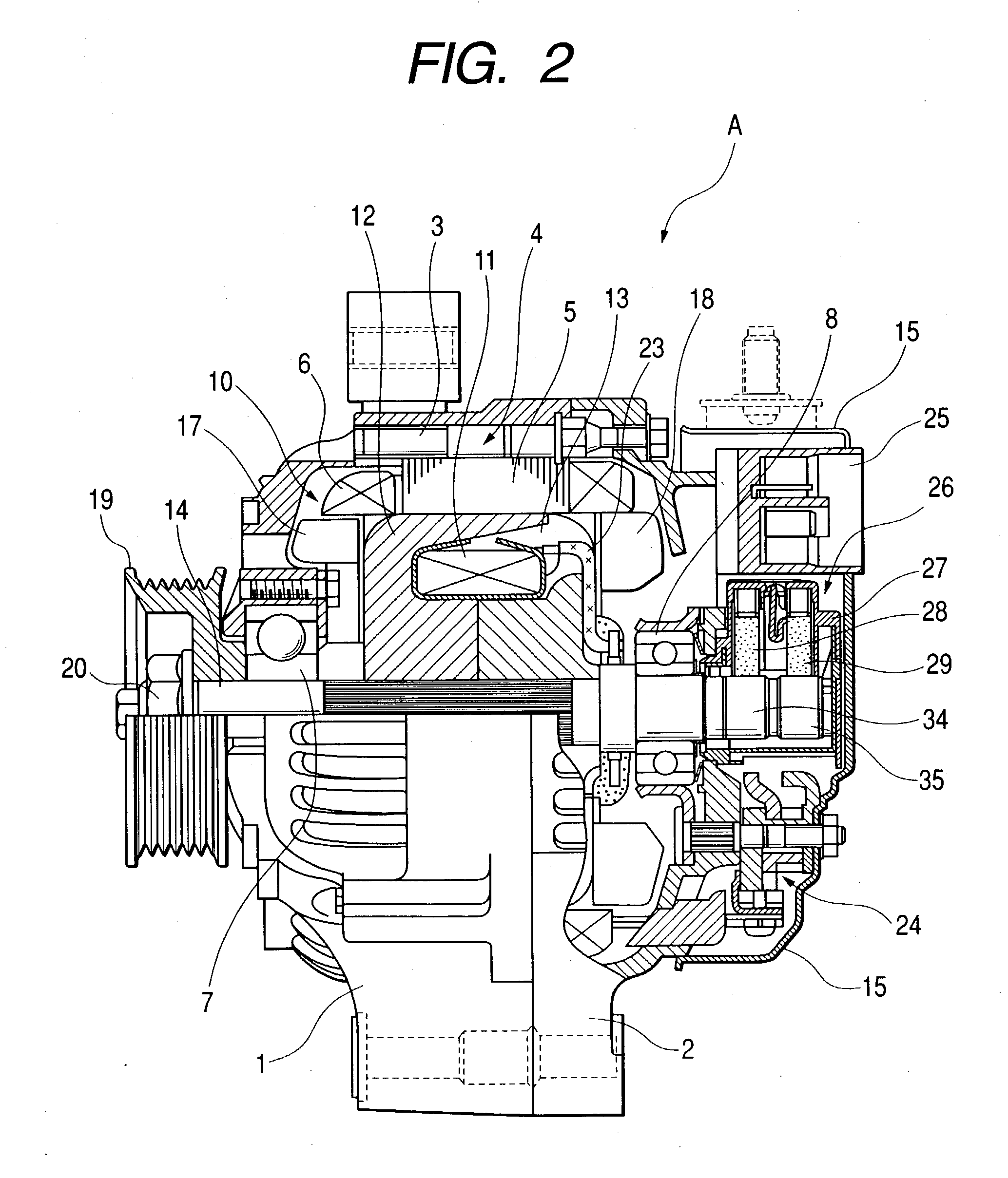
[0037] FIG. 2 is a cross-sectional view taken along the axis of rotation, corresponding to FIG. 1, showing the entire vehicle AC generator, designated by the letter A. The condition is shown in which the brush assembly 26 has been mounted on the vehicle AC generator apparatus A, with a brush support jig inserted. The front-end frame 1 and the rear-end frame 2 of the AC generator A, each formed of diecast aluminum, are disposed with respective open portions of these in mutual direct contact, attached by a plurality of bolts 3. A stator 4 is attached at the inner periphery of the front-end frame 1. The stator 4 is of known type, formed of a stator core 5 and a stator winding 6.

[0038] The rotor 10 is of known configuration, formed of a field winding 11, pole cores 12, 13, shaft 14, etc., and is rotatably supported by a pair of ball bearings 7, 8, which are respectively mounted in the front-end frame 1 and the rear-end frame 2. The radially extending faces of the pole cores 12, 13 have ...

second embodiment

[0061] Moreover with the second embodiment, the main body 62 is formed from sheet metal, with a narrow pin configuration, i.e., is of flat shape. However it would be equally possible to make the main body of greater width along the peripheral direction, shaped such as to follow the peripheries of the slip rings 34, 35 and the lower ends of the brushes 28, 29, i.e., formed with a curved shape such as would result from cutting an elongated section of a cylindrical tube along the axial direction of the tube. It will be apparent that this would enable the main body to be made greater in width, without requiring that the spacing between the brush holder and the slip rings be increased.

[0062] Furthermore with the above embodiments, the brush support jigs 51, 61 are each supported at support regions constituted by the holes 33b, 33d. which are formed in the slip ring cover 33. However it would be equally possible to provide a greater number of support regions, formed in the brush holder 27...


PUM


Abstract

A brush support jig for use during mounting of a brush assembly on a rotary electric machine having slip rings, to restrain the brushes against contact with the slip rings during the mounting operation, is of pin configuration having a linear portion formed of a linear portion made of a metal such as steel and a coating portion made of a material such as synthetic resin, having a lower degree of hardness than the slip rings, which covers the linear portion and thereby prevents damage to the slip rings in the event that that brush support jig comes into contact with the slip rings during the mounting operation

Description

[0001] 1. Field of Application[0002] The present invention relates to a brush support jig which is used when mounting the brush assembly of a rotary electric machine, and to a method of mounting a brush assembly by using such a brush support jig.[0003] 2. Related Prior Art[0004] In a rotary electric machine having slip rings and brushes which respectively contact the slip rings, such as an AC generator of a motor vehicle, a brush assembly is mounted on the machine, which includes a brush holder for supporting the brushes and also includes a slip ring cover which is of box configuration and which, together with the brush holder, surrounds the peripheries of the slip rings. If there is a defect such as a surface scratch in the slip rings, then this can cause abnormal noise to be generated and can result in shortening of the operating life of the brushes. For that reason, it is important to ensure that no damage occurs to the slip rings when the brush assembly is being mounted.[0005] V...

Claims


Application Information

Patent Timeline
IPC IPC(8): H02K5/14H02K13/00H02K15/02
CPCH02K2205/06H02K5/141H02K13/00
Inventor TSUGE, TAKAFUMIISHIKAWA, HIROAKI
Owner DENSO CORP
Learn More