
Device for locking cap nut for coupling

Inactive Publication Date: 2003-08-28
DEUTSCHE MONTAN TECHNOLOGIES GMBH
View PDF0 Cites 9 Cited by
  • Summary
  • Abstract
  • Description
  • Claims
  • Application Information

AI Technical Summary

Benefits of technology

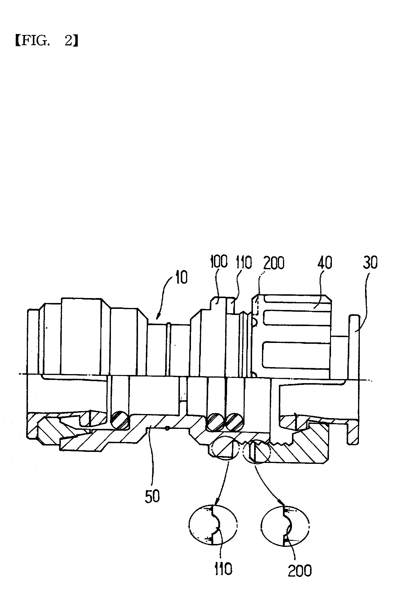
[0017] Additionally, in order to prevent the cap nut 40 from being released when the coupling 10 is applied to a vibrated product, the present invention includes a hooking plate 100 extended out of the body 50 which is connected to the metallic connecting pipe 20, hooking protrusions 110 protruded from the hooking plate 100 at a regular space, and hooking grooves 200 formed at a position facing the hooking protrusion 110 and engaged with the hooking protrusion 110 to prevent the cap nut 40 from being released when screwing the cap nut 40.
[0018] At this time, though it is described that the hooking groove 200 is formed at the cap nut 40 and the hooking protrusion 110 is formed at the body 50, it is not limited with this configuration. If preventing the cap nut 40 from being unscrewed, it is also possible to form the hooking protrusion at the cap nut 40 and the hooking groove at the body 50. In addition, the hooking protrusion 110 and the hooking groove 200 have an outer appearance of semi-circle or rounded so that the cap nut 40 may be smoothly assembled or disassembled.

Problems solved by technology

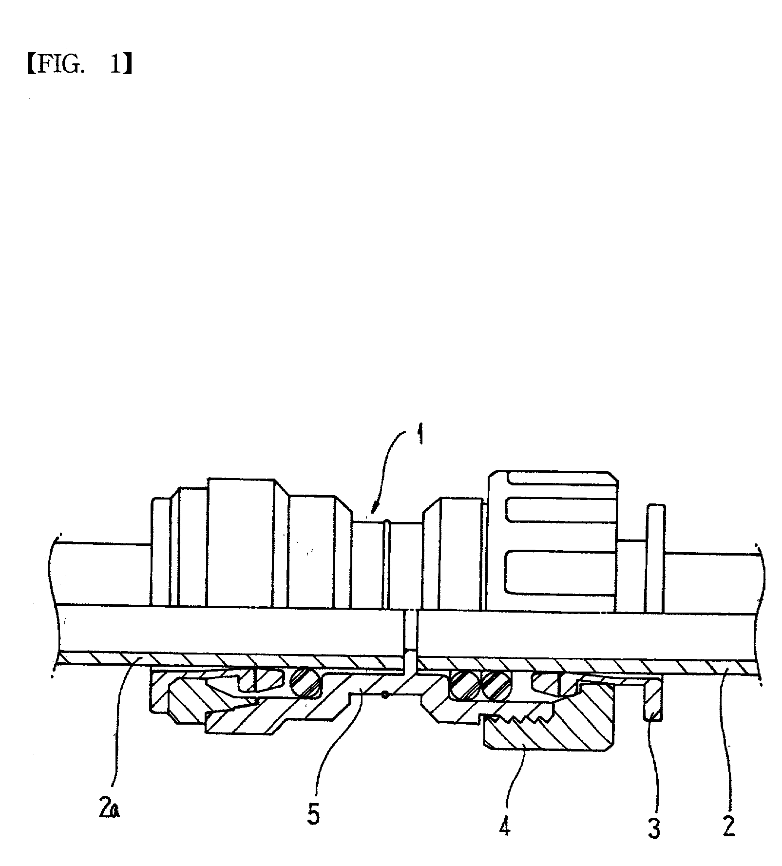
However, when the coupling 1 is applied to a vibrated product, it is possible that the screwed cap nut 4 is released due to continuous vibration for a long time because the coupling 1 does not have any locking device to prevent release of the cap nut 4.

Method used


Image

  • Device for locking cap nut for coupling
  • Device for locking cap nut for coupling
  • Device for locking cap nut for coupling

Examples


Embodiment Construction

[0014] Hereinafter, preferred embodiments of the present invention will be described in detail with reference to the accompanying drawings.

[0015] FIG. 2 is a sectional view showing a coupling to which a locking device of the present invention is applied, FIG. 3 is a sectional view showing that the coupling is combined with connecting pipes according to the present invention, FIG. 4 is a side view showing a hooking groove formed at a cap nut according to the present invention, and FIG. 5 is a side view showing a hooking protrusion formed at a body according to the present invention.

[0016] In the present invention, the coupling 10 includes a body 50, which is connected to a connecting pipe 21 made of synthetic resin at one side and a connecting pipe 20 made of metal at the other side, and a cap nut 40 screwed with the body 50 when the metallic connecting pipe 20 is inserted into the body 50 for pressing a collet 30 to prevent the connecting pipe 20 from being deviated from the body 50...


PUM


Abstract

A device for locking a cap nut for a coupling includes a hooking plate 100 extended out of the body 50 connected to the metallic connecting pipe 21, a plurality of hooking protrusions 110 protruded from the hooking plate 100 at a regular space, and a plurality of hooking grooves 200 formed at a position facing the hooking protrusion 110 and engaged with the hooking protrusion 110 to prevent the cap nut 40 from being released when screwing the cap nut 40, so as to prevent the cap nut 40 from being released, so eventually securely assembling the connecting pipes 21 not to be separated from the coupling 10.

Description

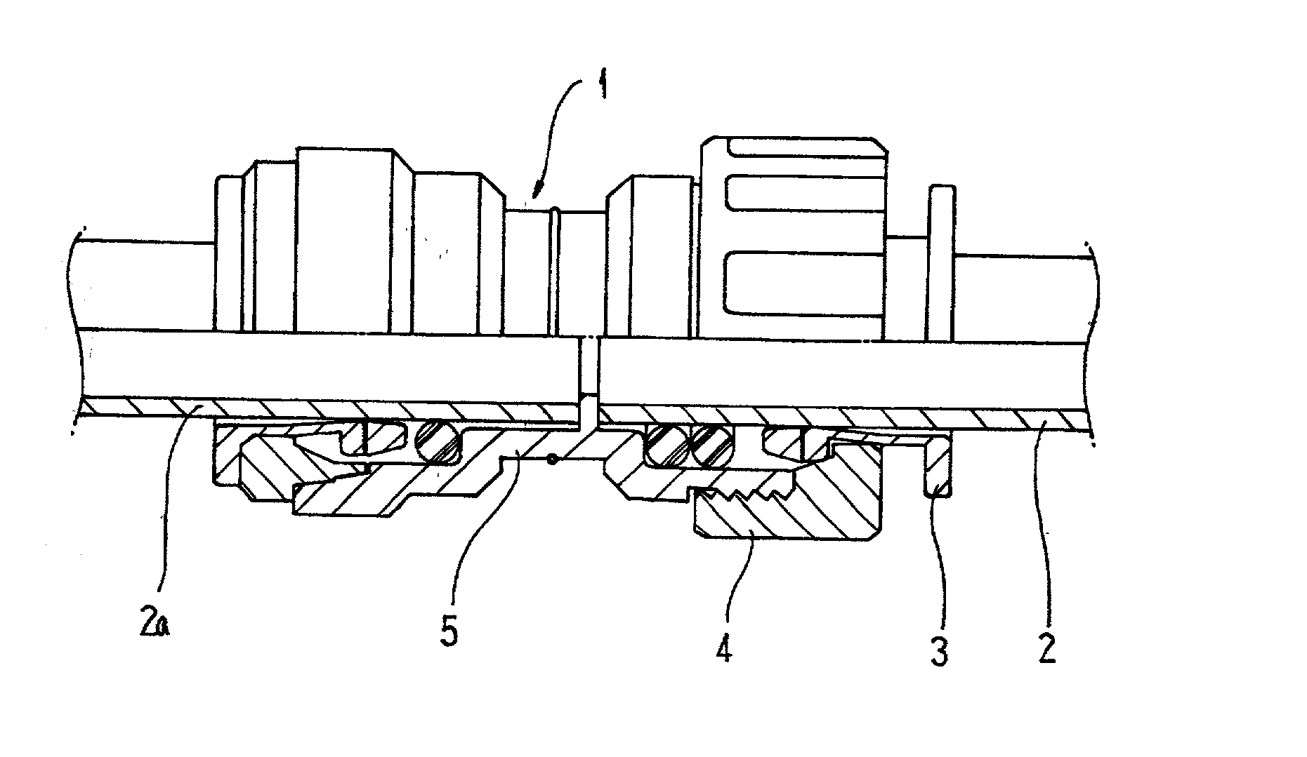
[0001] The present invention relates to a device for locking a cap nut fo a coupling, and more particularly to a device for locking a cap nut for a coupling, which is applied to the cap nut screwed with a body so as to prevent the cap nut from being released, so eventually securely assembling the connecting pipes not to be separated from the coupling.BACKGROUND OF THE INVENTIOON[0002] Generally, a coupling is used for connecting pipes made of synthetic resin or metal used for a water purifier or chemical delivery. Such a coupling is required to be easily connected to the pipes, maintain sufficient watertight and sealing characteristics, and be securely fixed.[0003] A conventional coupling 1 is shown in FIG. 1, and now described below in brief. As shown in FIG. 1, the coupling 1 includes a body 5, which is, at one side, connected to a connecting pipe 2a made of synthetic resin and, at the other side, connected to a connecting pipe 2 made of metal, and a cap nut 4 screwed with the bod...

Claims


Application Information

Patent Timeline
IPC IPC(8): F16L37/12F16L19/00
CPCF16L2201/20F16L19/005
Inventor MIN-CHEOL, CHOE
Owner DEUTSCHE MONTAN TECHNOLOGIES GMBH
Learn More