Eureka AIR delivers breakthrough ideas for toughest innovation challenges, trusted by R&D personnel around the world.

Method for operating a burner and burner with stepped premix gas injection

Inactive Publication Date: 2003-08-14
ANSALDO ENERGIA SWITZERLAND AG
View PDF2 Cites 63 Cited by
  • Summary
  • Abstract
  • Description
  • Claims
  • Application Information

AI Technical Summary

Benefits of technology

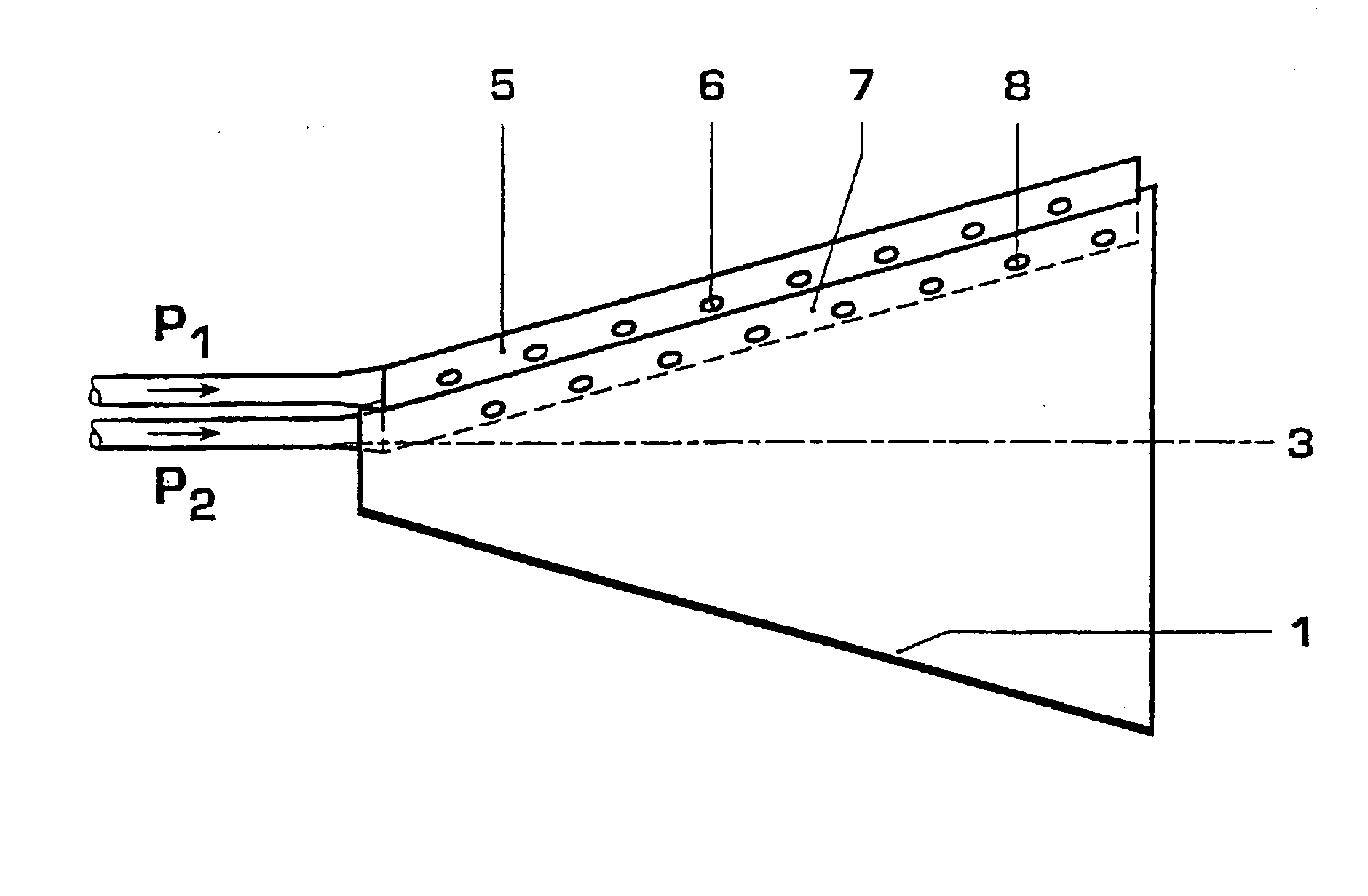
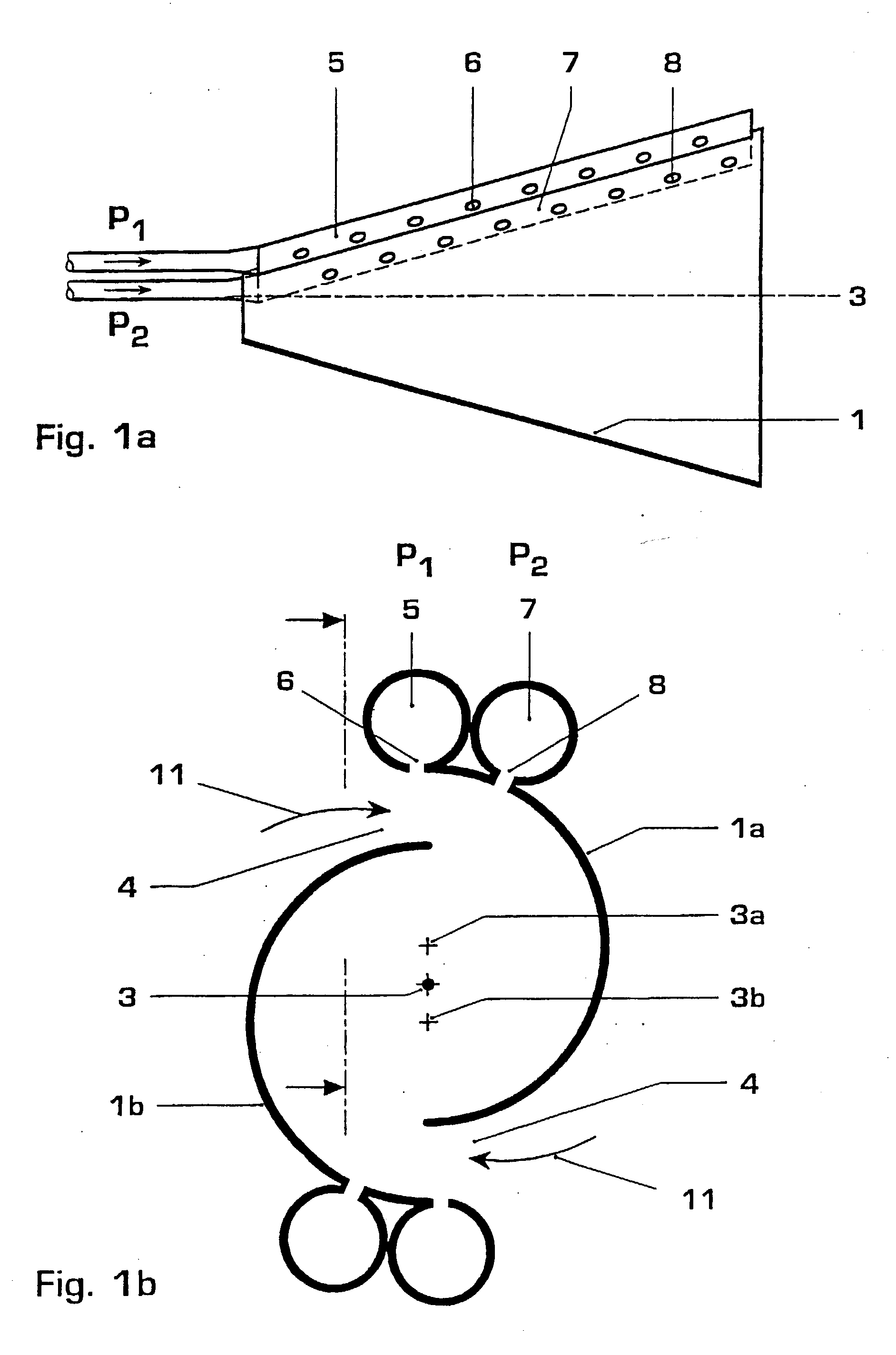
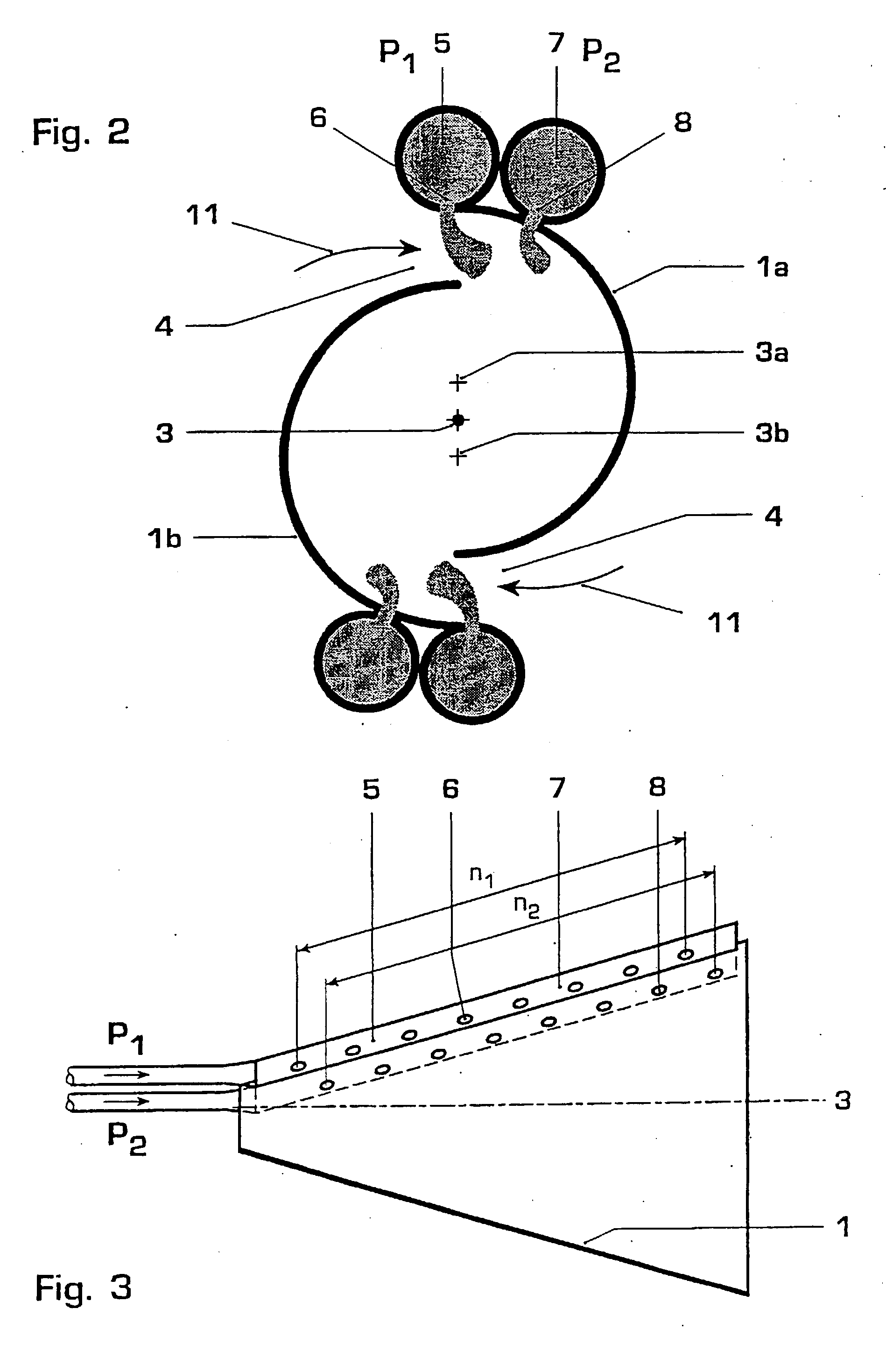
[0019] The one or a plurality of second fuel supply conduits, by means of which the quantity--and therefore also the upstream fuel pressure--of premix fuel which is injected into the swirl space via the second group of fuel outlet openings can be set independently of the quantity of premix fuel which flows via the first fuel supply conduits, make possible a simple matching of the mixture distribution and the mixture quality to different boundary conditions. In addition, this design also makes it possible to achieve compensation for different Wobbe indices by, for example, the first fuel supply conduits supporting a certain power or a certain volume flow and the rest of the power or the volume flow being operated by means of the second fuel supply conduits. The axial and radial fuel distribution in the burner can be favorably influenced by appropriate arrangement of the second fuel supply conduits, with the corresponding second group of fuel outlet openings, relative to the first fuel supply conduits, with the first group of fuel outlet openings. It is therefore possible to achieve a specified enrichment of the mixture with fuel in certain regions of the burner outlet, during part-load operation, in order to improve the flame stability. At high burner load, the fuel can then be uniformly distributed, which results in low emissions.

Problems solved by technology

The supply of the pilot gas in the outlet region of the burner leads, however, to increased NO.sub.x emissions because it is only inadequate mixing with the combustion air which can take place in this region.
The known burners can therefore only be operated optimally for quite specific value ranges of these parameters.
A problematic feature in the operation of premix burners, particularly in gas turbines, is the part-load range because, in this range, the combustion air is mixed with only comparatively small fuel quantities.
In the case of the complete mixing of the fuel with the whole of the air, however, a mixture occurs which is no longer capable of being ignited, particularly in the lower part-load range, or is only capable of forming a very unstable flame.
This can lead to damaging combustion pulsations or to the flame becoming completely extinguished.
This, however, is only possible in the case of multi-row burner arrangements.
In the case of single-row annular combustion chambers, this technology has the disadvantage that a temperature profile, which is non-uniform in the peripheral direction, appears at the combustion chamber outlet.
This results, on the one hand, in superior flame stability but, on the other, in high emission values and further technical disadvantages in operation.

Method used


Image

  • Method for operating a burner and burner with stepped premix gas injection
  • Method for operating a burner and burner with stepped premix gas injection
  • Method for operating a burner and burner with stepped premix gas injection

Examples


Embodiment Construction

[0044] The following figures show the burners in strongly diagrammatic embodiment, so that only the features essential for the respective explanation are emphasized in each case. The specialist is familiar with the further arrangement of the burners represented, inter alia from the documents cited as the prior art, which represent an integrated constituent of the present description. In addition, reference is made in some cases to the injection of gaseous fuel in the exemplary embodiments. It is, however, obvious per se that liquid fuels can also be introduced into the combustion air flow via the fuel outlet openings. The fuel is, in addition, referred to as premix fuel; it is obvious per se that a part of the total fuel quantity can also be introduced in certain load ranges as pilot fuel in order to further increase the flame stability. No supply conduits for pilot fuel are shown in any of the figures because they are not essential to the invention; given knowledge of the prior art...


PUM


Abstract

The present invention relates to a method of operating a burner, which comprises at least one first fuel supply conduit (5) with a first group of fuel outlet openings (6), essentially arranged in the direction of a burner longitudinal axis (3), for a first premix fuel quantity and one or a plurality of second-fuel supply conduits (7) with a second group of fuel outlet openings (8), essentially arranged in the direction of the burner longitudinal axis (3), for a second premix fuel quantity, it being possible to admit fuel to the second fuel supply conduits (7) independently of the first fuel supply conduit (5). In the method, both fuel supply conduits (5, 7) are operated with the same fuel. By means of the present method of operating a burner, optimum mixing conditions can be set even in the case of different loads, gas qualities or gas preheat temperatures.

Description

TECHNICAL FIELD OF APPLICATION[0001] The present invention relates to a method of operating a burner, which has at least one first fuel supply conduit with a first group of fuel outlet openings, essentially arranged in the direction of a burner longitudinal axis, for the introduction of a first premix fuel quantity into a swirl space and one or a plurality of second fuel supply conduits with a second group of fuel outlet openings essentially arranged in the direction of the burnerlongitudinal axis, it being possible to admit fuel to the second fuel supply conduits independently of the first fuel supply conduit. The invention also relates to a burner which can be advantageously operated by means of the method. The combustion spaces of gas turbines are a preferred field of employment for such burners; in addition such burners are, for example, also employed in atmospheric boiler firing systems.PRIOR ART[0002] A conical burner consisting of a plurality of shells, a so-called double-con...

Claims


Application Information

Patent Timeline
IPC IPC(8): F02C9/26F23C7/00F23C99/00F23D14/02F23D14/24F23D17/00F23R3/12F23R3/28F23R3/32F23R3/34
CPCF23C7/002F23C2900/07002F23R3/286F23D2900/14021F23D17/002
Inventor EROGLU, ADNANHELLAT, JAANSTUBER, PETER
Owner ANSALDO ENERGIA SWITZERLAND AG
Why Eureka
Eureka Blog
Learn More