
Novel interconnection structures and methods of fabrication

a technology of interconnection structure and fabrication method, which is applied in the field of multi-level integrated circuits, can solve the problems of open circuits and other reliability problems, affecting the performance and reliability of fabricated circuits, and both reliability and performance problems in fabricated integrated circuits

Inactive Publication Date: 2003-08-07
INTEL CORP
View PDF20 Cites 15 Cited by
  • Summary
  • Abstract
  • Description
  • Claims
  • Application Information

AI Technical Summary

Benefits of technology

The solution improves the reliability and performance of ULSI circuits by reducing current crowding, preventing electromigration, and maintaining redundant current paths, ensuring high density and planarity, even at small dimensions.

Problems solved by technology

The quality of the interconnection structure drastically affects the performance and reliability of the fabricated circuit.
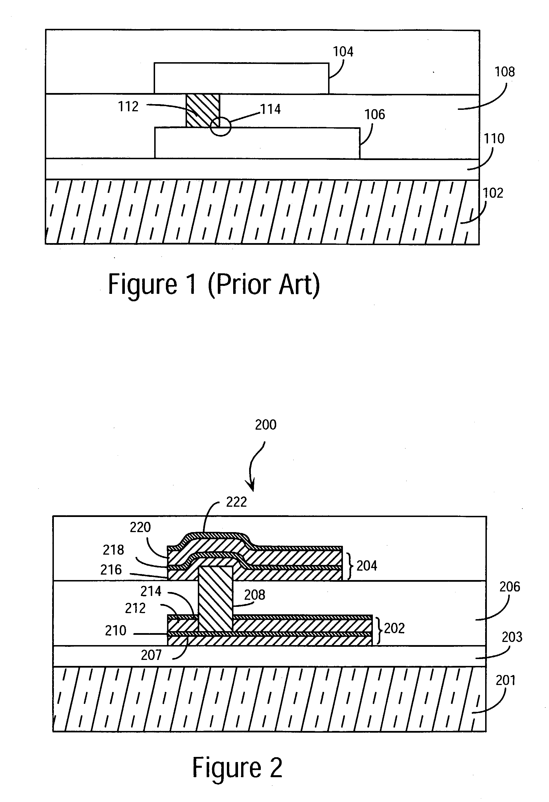
The interconnection structure of FIG. 1 experiences several problems.
Such small vias can cause both reliability and performance problems in a fabricated integrated circuit.
Current crowding in area 114 can cause self-heating effects which can cause electromigration.
Electromigration can cause voids and open circuits and other reliability problems.
Another problem with the interconnection structure of FIG. 1 is the aluminum metal used for interconnections 104 and 106.
Aluminum interconnections are known to suffer from electromigration.
Electromigration in interconnections are known to cause voids which can cause open circuits and failures.
Aluminum interconnections are also known to form hillocks which can result in nonplanar interconnection structures and can cause interlevel shorts with interconnections formed above and intralevel shorts with neighboring interconnection lines from the same level of metalization.
These problems are magnified as line widths decrease and packing densities increase as in the case of future ULSI circuits.

Method used


Image

  • Novel interconnection structures and methods of fabrication
  • Novel interconnection structures and methods of fabrication
  • Novel interconnection structures and methods of fabrication

Examples


Embodiment Construction

[0031] The present invention describes a novel, high density, high reliability, high performance interconnection structure with a ULSI manufacturable process. In the following description numerous specific details are set forth such as materials thicknesses and types in order to provide a thorough understanding of the present invention. It will be obvious, however, to one skilled in the art that the present invention may be practiced without these specific details. In other instances, well-known semiconductor manufacturing processes and equipment have not been set forth in detail in order to not unnecessarily obscure the present invention.

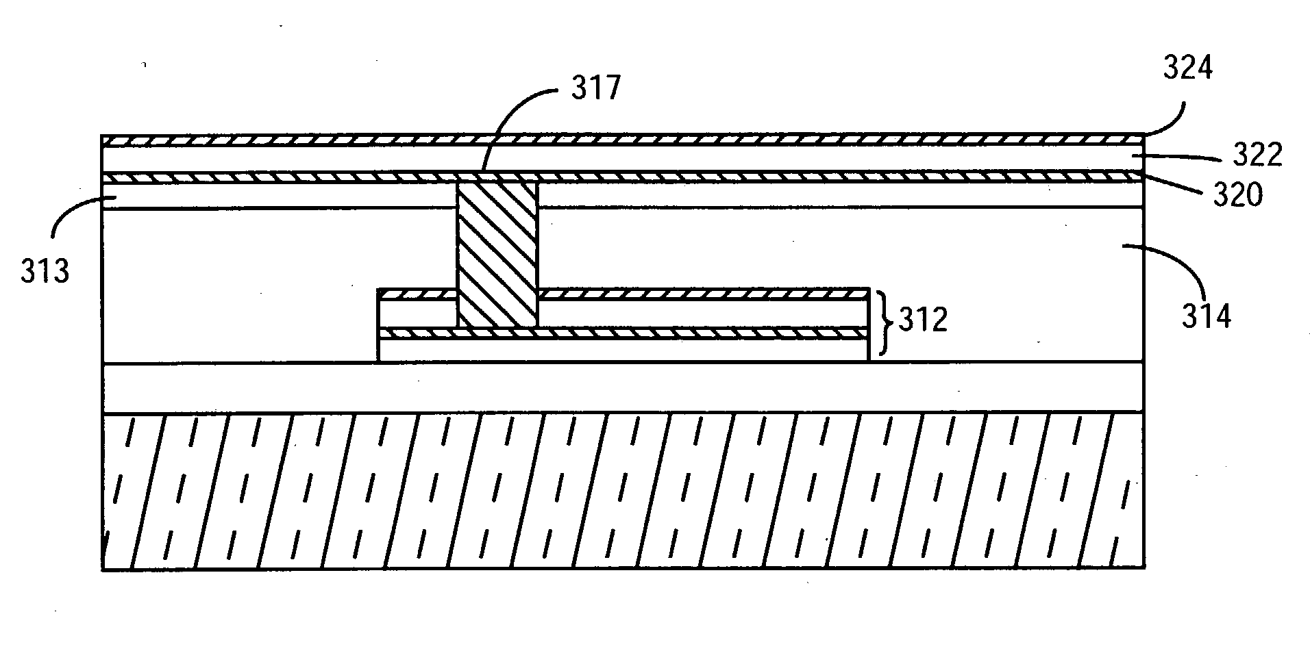
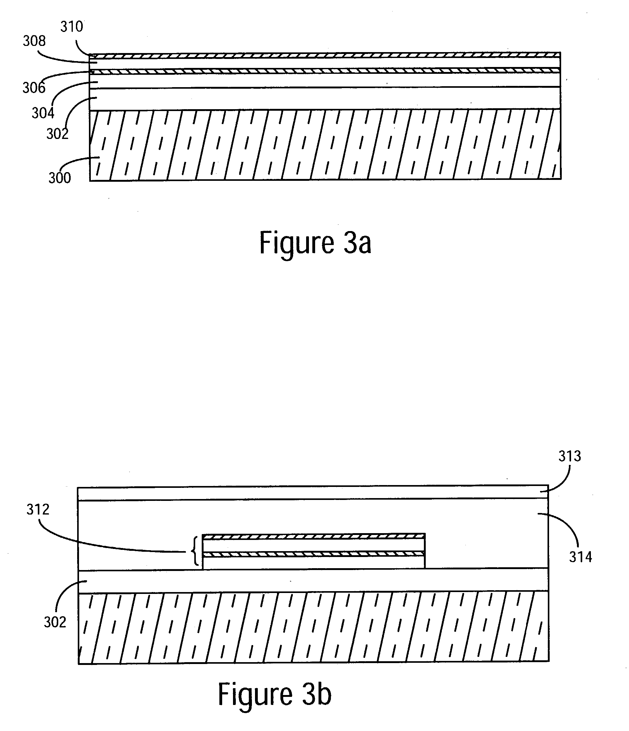
[0032] A preferred embodiment of the present invention is shown in FIG. 2. The present invention is a multilevel interconnection structure 200 which is ideal for high density, high reliability, and high performance integrated circuits. Interconnection structure 200 comprises interconnections 202 and 204. Interconnection structure 200 is formed on a...


PUM

PropertyMeasurementUnit
thicknessaaaaaaaaaa
thicknessaaaaaaaaaa
insulatingaaaaaaaaaa

Abstract

A novel, high performance, high reliability interconnection structure for an integrated circuit. The interconnection structure of the present invention is formed on a first insulating layer which in turn is formed on a silicon substrate or well. A first multilayer interconnection comprising a first aluminum layer, a first refractory metal layer, and a second aluminum layer is formed on the first insulating layer. A second insulating layer is formed over the first multilayer interconnection. A conductive via is formed through the second insulating layer and recessed into the first multilayer interconnection wherein a portion of the via extends above the second insulating layer. A second interconnection is formed on the second insulating layer and on and around the portion of the via extending above the second insulating layer.

Description

CROSS REFERENCE TO RELATED PATENT APPLICATION[0001] This application is a continuation-in-part of patent application Ser. No. 08 / 175,053 filed on Dec. 29, 1993, for "High Surface Area Via Structure for Interconnection and Method of Fabrication" by Donald S. Gardner.[0002] 1. Field of the Invention[0003] The present invention relates to the field of multilevel integrated circuits, and more specifically, to the field of ULSI multilevel interconnection structures and their methods of fabrication.[0004] 2. Discussion of Related Art[0005] Modem integrated circuits are made up of literally millions of active devices such as transistors and capacitors. These devices are initially isolated from one another but are later interconnected together to formed functional circuits. The quality of the interconnection structure drastically affects the performance and reliability of the fabricated circuit. Interconnections are increasingly determining the limits of performance and density of modern ul...

Claims


Application Information

Patent Timeline
Patent Type & Authority Applications(United States)
IPC IPC(8): H01L21/768H01L23/522H01L23/532H04J3/06H04L12/56H04Q11/04
CPCH01L21/76805H01L21/76838H01L21/76877H01L23/5226H04Q11/0478H04J3/0632H04J2203/0089H04L2012/5652H04L2012/5672H01L23/53223H01L2924/0002H01L2924/00
Inventor GARDNER, DONALD S.
Owner INTEL CORP
Learn More