Disk drive device, actuator lock mechanism, inertia latch mechanism and inertia lever

Inactive Publication Date: 2003-08-07
WESTERN DIGITAL TECH INC
View PDF3 Cites 8 Cited by
  • Summary
  • Abstract
  • Description
  • Claims
  • Application Information

AI Technical Summary

Benefits of technology

[0017] Here, the conventional inertia latch mechanism has employed a structure of rotatably supporting the inertia member on the pin. Therefore, it is supposed that the inertia member moves in a vertical direction by vibrations applied thereto and collides with a case of the disk drive device. There has been a possibility that this collision causes contamination. On the contrary, in the disk drive device according to the present invention, for the inertia member, flexure to the swing direction in the latch member is permitted, but the inertia member is connected to the elastic member in which the flexure to the direction perpendicular to the swing direction is substantially limited. Therefore, the vibration of the inertia member in the vertical direction is limited. Accordingly, the collision of the inertia member with the case of the disk drive device can be suppressed.
[0020] Note that, as described in an embodiment to be described later, structures of the latch member and the inertia member are determined, and thus the inertia member can restrict the movement of the latch member to the direction perpendicular to the swing direction.

Problems solved by technology

During the non-operation of the disk drive device, if the head slider mounted on the actuator moves (pops out) from an escape position to a data area on the disk surface by the impact, then the head slider is stuck to the surface of the data area, or damages the surface of the data, resulting in a fatal failure.
However, for a large impact, it is difficult for only the lock mechanism formed of the ramp to prevent the actuator from popping out.
However, work of erecting a pin as this swing shaft is not easy.
Particularly, in a small size disk drive device mounted on the portable PC, since the pin itself is in small diameter, workability therefor is poor, and a position of erecting the pin must be determined with high accuracy.
Moreover, for the elastic member, flexure to a swing direction of the latch member is permitted, but flexure to a direction perpendicular to the swing direction is substantially limited.
There has been a possibility that this collision causes contamination.
Therefore, the vibration of the inertia member in the vertical direction is limited.
If a regulating member is provided, which permits the swing of the inertia member, and more specifically, the inertia lever, but regulates the operation of the inertia lever to directions other than the swing direction, then the vibrations of the inertia member in the vertical direction can be limited.

Method used


Image

  • Disk drive device, actuator lock mechanism, inertia latch mechanism and inertia lever
  • Disk drive device, actuator lock mechanism, inertia latch mechanism and inertia lever
  • Disk drive device, actuator lock mechanism, inertia latch mechanism and inertia lever

Examples


Embodiment Construction

[0038] Hereinafter, description will be made in detail for the present invention based on an embodiment.

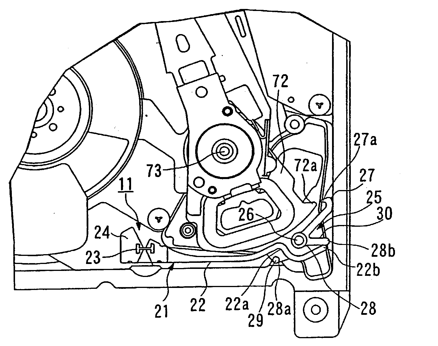
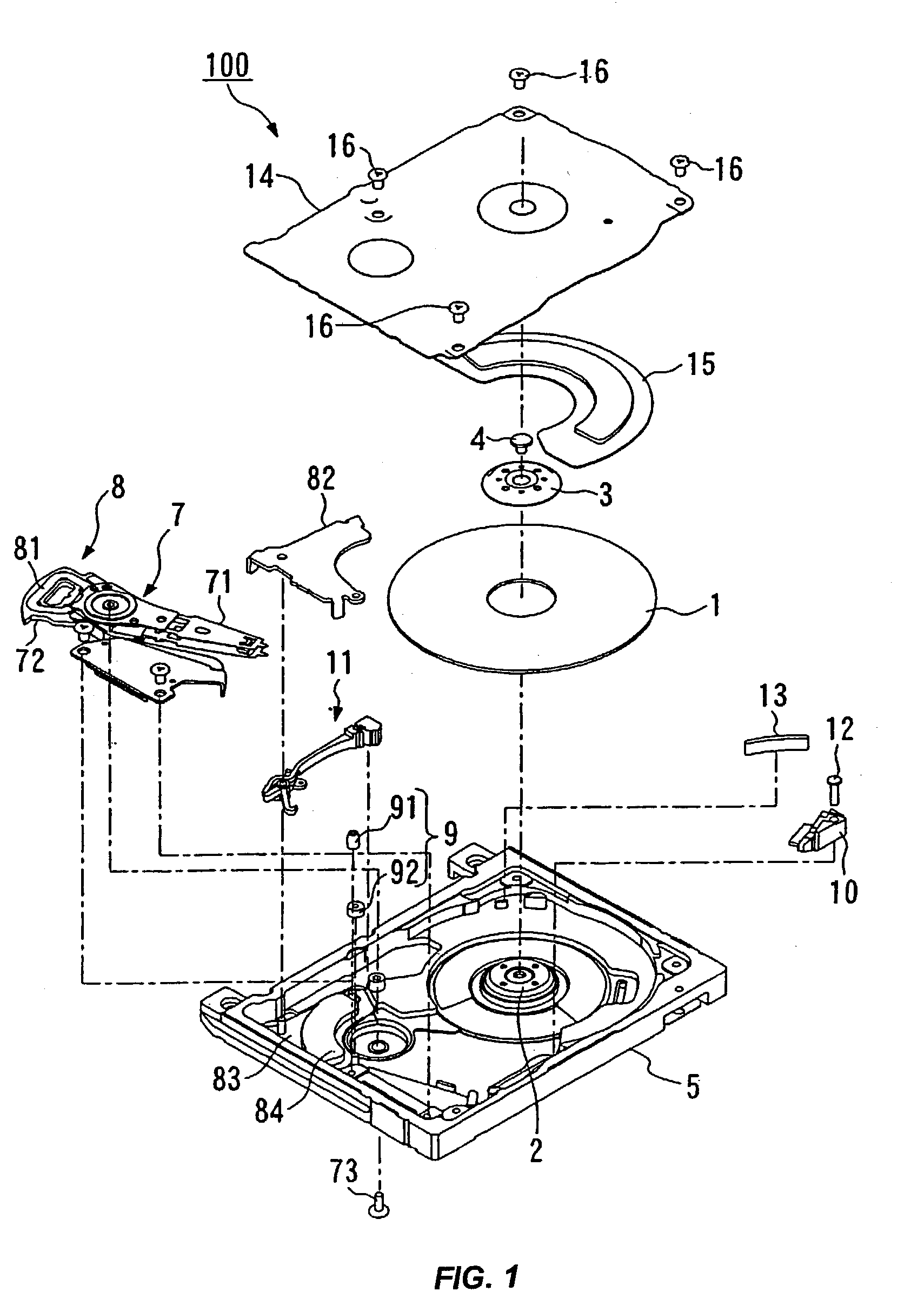
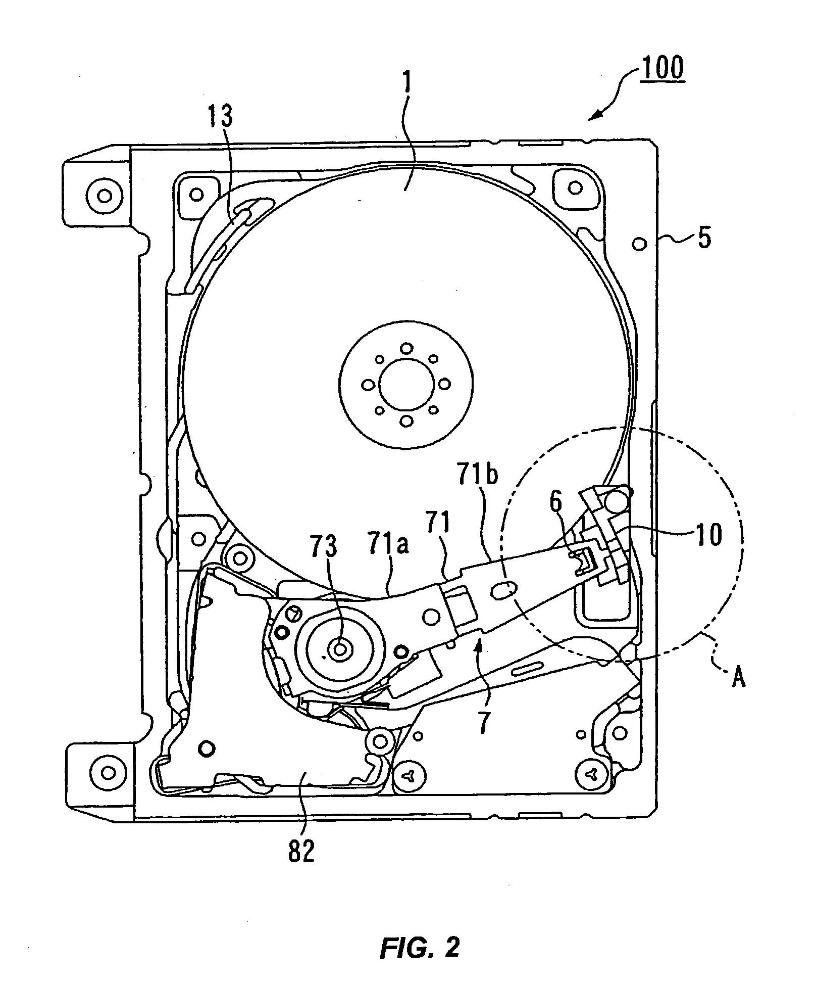
[0039] FIG. 1 is an exploded perspective view of a hard disk drive 100 as a disk drive device according to the embodiment of the present invention, FIG. 2 is a plan view of the hard disk drive 100, and FIG. 3 is an enlarged view of a portion A of FIG. 2. Note that FIG. 2 shows a state where a top cover 14 of the hard disk drive 100 is removed.

[0040] In FIGS. 1 to 3, in a box-shaped base 5, there are accommodated a magnetic disk 1 as a data recording medium, a spindle motor 2 for rotatively driving the magnetic disk 1, an actuator 7 having head sliders 6 mounted thereon, a voice coil motor (VCM) 8 for swingingly driving the actuator 7, a crush stop 9 for regulating a swing range of the actuator 7, a ramp block 10 provided in an escape position for the actuator 7, an inertia latch mechanism 11 of the present invention, which constitutes an actuator lock mechanism, and the like. This...


PUM


Abstract

Disclosed is an inertia latch mechanism capable of omitting erection of a pin for swinging an inertia lever. An inertia lever for use in the inertia latch mechanism is constituted of: a lever body swinging by inertia when an impact is applied thereto; a fixture fixed to a case of a disk drive device; and a plate spring member for connecting the lever body and the fixture and permitting swing of the lever body.

Description

RELATED PATENT APPLICATION[0001] This application claims the priority of Japanese Patent No. JP2002-025925 (IBM Docket No. JP920010389JP1), filed on Feb. 1, 2002, and entitled "Disk Drive Device, Actuator Lock Mechanism, Inertia Latch Mechanism and Inertia Lever".[0002] 1. Technical Field[0003] The present invention relates to an inertia latch mechanism for latching an actuator of a disk drive device when an impact is applied from the outside to the disk drive device, and more particularly, to an installation structure of an inertia lever for use in the inertia latch mechanism.[0004] 2. Description of the Related Art[0005] In the disk drive device in recent years, for the purpose of preventing sticking of a head slider to a surface of a disk and enhancing a reliability for an impact applied thereto, a load / unload mechanism for the head slider has been employed. During nonoperation of the disk drive device, the load / unload mechanism allows a part called a ramp, which is provided in t...

Claims


Application Information

Patent Timeline
IPC IPC(8): G11B21/22G11B5/54G11B21/02
CPCG11B5/54
Inventor HASHIZUME, MASATAKAKIMURA, SHINICHITAKAHASHI, KOHJI
Owner WESTERN DIGITAL TECH INC
Why Eureka
Try Eureka