Cutting insert, cutting tool, and cutting method using the cutting tool
A technology for cutting inserts and cutting tools, used in milling cutting inserts, manufacturing tools, milling cutters, etc., can solve the problem of chips colliding with each other, and achieve the effect of reducing cutting resistance and excellent chip discharge.
- Summary
- Abstract
- Description
- Claims
- Application Information
AI Technical Summary
Problems solved by technology
Method used
Image

Examples
no. 1 approach
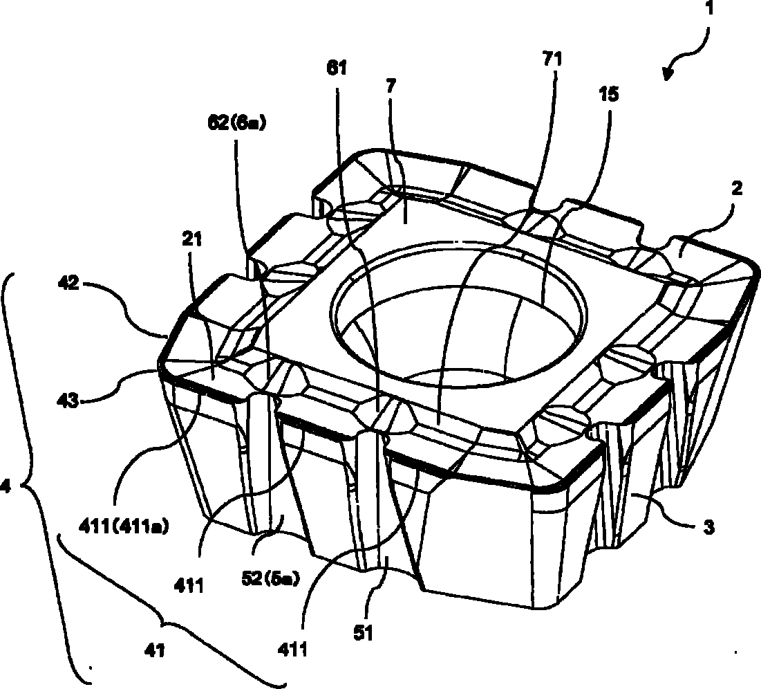
[0023] Figure 1 to Figure 3 It is a figure which shows one embodiment of this invention.
[0024] The insert 1 has an upper surface 2 , a side surface 3 , and a cutting edge 4 provided at the intersection of the upper surface 2 and the side surface 3 . The upper surface 2 constitutes a substantially polygonal shape, specifically, a substantially quadrangular shape. Furthermore, the insert 1 has a rake region 21 extending inwardly from the cutting edge 4 on the upper surface 2 .
[0025] In this embodiment, the cutting edge 4 has a first cutting edge 41 , a second cutting edge 42 , and a third cutting edge 43 connected to the first cutting edge 41 and the second cutting edge 42 .
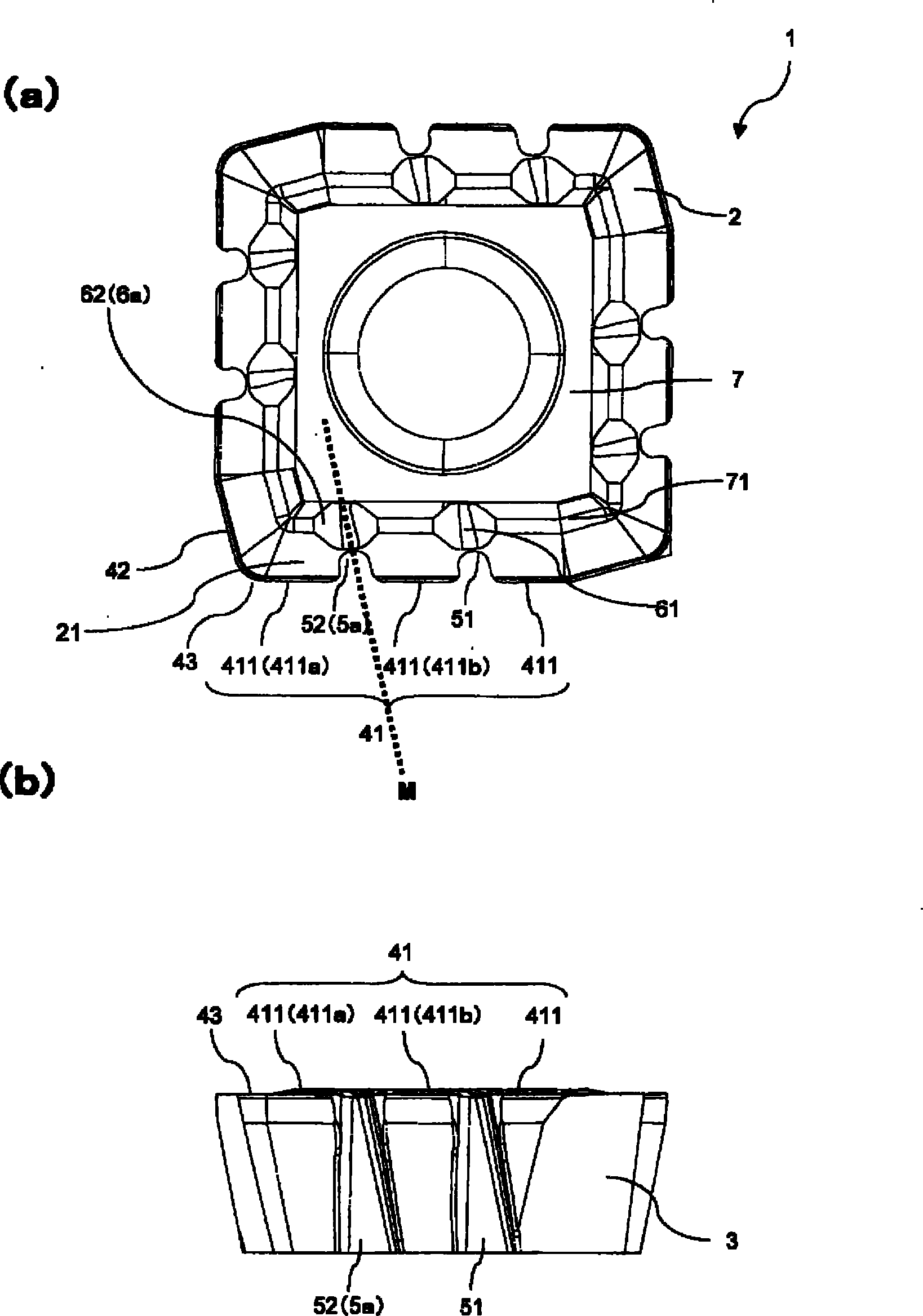
[0026] Such as figure 2 As shown in (a), the first cutting edge 41 is located at a first intersection portion where the upper surface 2 and the first side surface 3 intersect. That is, it is located on one side of the upper surface 2 constituting a substantially quadrangular shape. Furthermore...
no. 2 approach
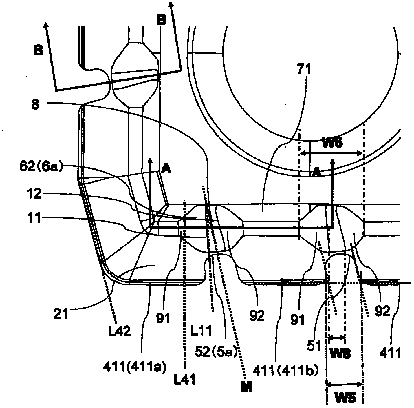
[0082] Such as Figure 5 and Figure 6 As shown, the insert 1' of the present embodiment differs from the insert 1 of the first embodiment in the number of grooves 5 that cut off the first cutting edge 41. Specifically, the insert 1 has two grooves 5 that cut off the first cutting edge 41, whereas the insert 1' has three grooves 5 that cut off the first cutting edge 41. That is, in the insert 1', the first cutting edge 41 is truncated into four small cutting edges 411.
[0083] In this embodiment, the distance between the corner groove portion 5a closest to the third cutting edge 43 among the three groove portions 5 and the third cutting edge 43 is smaller than that of the insert 1 of the first embodiment. That is, the corner groove portion 5 a of the present embodiment is provided closer to the third cutting edge 43 than the corner groove portion 5 a of the first embodiment described above.
[0084] In addition, in the first embodiment, the two groove portions 5 including ...
PUM
 Abstract
Description
Claims
Application Information
 - R&D
- Intellectual Property
- Life Sciences
- Materials
- Tech Scout
- Unparalleled Data Quality
- Higher Quality Content
- 60% Fewer Hallucinations
Browse by: Latest US Patents, China's latest patents, Technical Efficacy Thesaurus, Application Domain, Technology Topic, Popular Technical Reports.
© 2025 PatSnap. All rights reserved.Legal|Privacy policy|Modern Slavery Act Transparency Statement|Sitemap|About US| Contact US: help@patsnap.com