
Methods and apparatus for controlling a pacing system in the presence of EMI

a pacing system and emi technology, applied in the field of electronic and medical devices, can solve the problems of complex pacing systems, complex tasks, and complex tasks, and achieve the effect of accurately generating sense events and accurate generating sense events

Active Publication Date: 2003-07-31
MEDTRONIC INC
View PDF3 Cites 226 Cited by
  • Summary
  • Abstract
  • Description
  • Claims
  • Application Information

AI Technical Summary

Benefits of technology

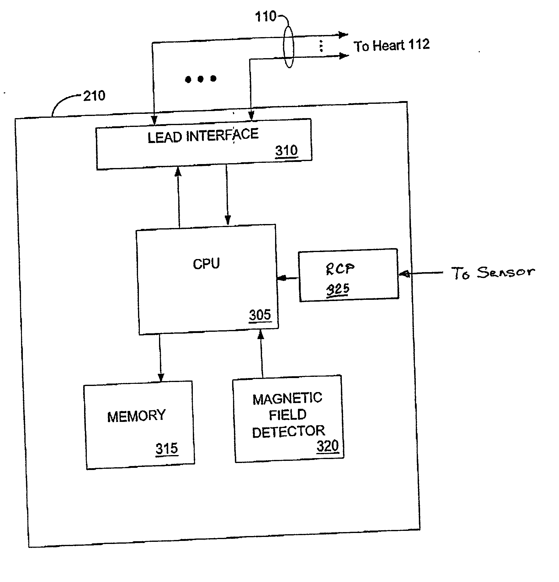
0036] FIG. 7 illustrates a process for controlling the pacing system of FIG. 1 in response to the presence of high frequency radiation interference signals according to another embodiment of the present invention;
0037] FIG. 8 illustrates a general process for establishing an interference state pacing mode and pacing rate of a pacing system operating in a single chamber pacing mode in response to an interference state caused by the presence of a form of EMI that affects the sense amplifiers ability

Problems solved by technology

State of the art IMDs are vastly more sophisticated and complex than earlier ones and are capable of performing significantly more complex tasks.
More complex pacing systems have been devised that automatically change pacing mode under certain circumstances.
Most incidences of exposure of patient-implanted pacemakers and ICDs to sources of EMI are inadvertent and unintentional.
However, such patients are often subjected intentionally to a variety of EMI sources including EMI emitted by other IMDs implanted in the same patient or external security equipment and medical equipment as reported in the Pinski et al. article.
The intense magnetic field emitted during an MRI scanning session (or other intense magnetic fields that the patient may inadvertently encounter) can cause currents to be induced in the conductors of the leads and other circuits or components coupled between the pace / sense electrodes and the sense amplifiers that distort or corrupt the EGM.
In addition, high frequency (HF) radiation interference signals produced by radar, mobile phone transmitters, and the like, typically cause the AN EGM to also become distorted and / or corrupted.
The distortion and corruption of the EGM presented to the sense amplifiers of such IMDs results in undersensing or oversensing P-waves and / or R-waves which can inhibit delivery of pacing or a cardioversion / defibrillation therapy, or inadvertently trigger delivery of high rate pacing or a cardioversion / defibrillation shock or cause pacemakers or ICD pacing systems to revert to a safe reversion mode as described above.
Thus, in one way or another, the sense amplifiers or sensing circuits cannot accurately sense the underlying heart rate during the MRI scanning session due to the response to the magnetic field and electromagnetic interference signals.
The patient's spontaneous heart rate can increase during the MRI scanning session and surpass a prevailing magnet mode pacing rate or reversion mode rate due to the patient's anxiety resulting in potentially harmful "parasystole" when the pacing system attempts to pace the heart at a rate lower than the patient's actual spontaneous heart rate.
Thus, parasystole is a highly undesirable condition potentially causing serious harm to the patient, including fatality.
Alternatively, the spontaneous heart rate may be considerably slower than the "magnet mode" pacing rate or the reversion pacing rate (whichever is controlling under the influence of the magnetic field or EMI, respectively), and, under magnet mode rate pacing, the heart may be overdriven (overdriven) at a harmful rate.
The heart rate increased by this mechanism can cause patients to experience angina, especially when the patient is suffering from coronary disease because higher heart rates shorten the diastolic interval during which the myocardium normally is perfused with blood, and un-physiologically high stimulation rates can drive such patients into myocardial infarction.
The patient may be adversely affected when the pacing rate abruptly switches to the pacing lower rate or an intermediate magnet mode or reversion rate that is lower than the prevailing physiologic pacing rate.
A patient could lose consciousness due to a sudden loss of blood pressure and be injured if driving a vehicle or involved in a stressful activity.

Method used


Image

  • Methods and apparatus for controlling a pacing system in the presence of EMI
  • Methods and apparatus for controlling a pacing system in the presence of EMI
  • Methods and apparatus for controlling a pacing system in the presence of EMI

Examples


Embodiment Construction

and the preferred embodiments follow, after a brief description of the drawings, wherein additional advantages and features of the invention are disclosed.

[0028] This summary of the invention has been presented here simply to point out some of the ways that the invention overcomes difficulties presented in the prior art and to distinguish the invention from the prior art and is not intended to operate in any manner as a limitation on the interpretation of claims that are presented initially in the patent application and that are ultimately granted.

[0029] The invention may be understood by reference to the following description taken in conjunction with the accompanying drawings, in which the leftmost significant digit(s) in the reference numerals denote(s) the first figure in which the respective reference numerals appear, and in which:

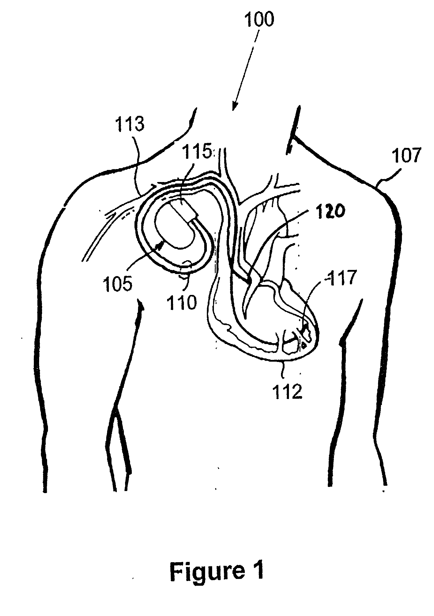
[0030] FIG. 1 schematically illustrates one example of a pacing system in which the present invention can be implemented comprising a pacemaker impla...


PUM


Abstract

Pacing systems are disclosed including detectors for detecting the presence of electromagnetic interference and setting an interference state pacing mode and pacing rate. The interference state pacing mode and pacing rate are altered as a function of patient pacemaker dependency and the prevailing mean heart rate. When pacemaker dependency exists, the pacing rate is maintained and even increased from the prevailing mean heart for the duration of the interference state. When the patient is determined to not be pacemaker dependent, pacing is inhibited or suspended for the duration of the interference state.

Description

[0001] This application is a continuation-in-part of U.S. patent application Ser. No. 10 / 059,586 filed Jan. 29, 2002 for METHOD AND APPARATUS FOR CONTROLLING AN IMPLANTABLE MEDICAL DEVICE IN RESPONSE TO THE PRESENCE OF A MAGNETIC FIELD AND / OR HIGH FREQUENCY RADIATION INTERFERENCE SIGNALS (P-8110.00) in the name of Hermann D. Funke.[0002] This invention relates generally to implantable medical devices and, more particularly, to a method and apparatus for controlling a pacemaker in response to the presence of a relatively strong magnetic field produced by magnetic resonance imaging (MRI) signals and / or high frequency radiation interference signals and other forms of electromagnetic interference (EMI) comprising an interference state.DESCRIPTION OF THE RELATED ART[0003] Considerable advances have been made in the fields of electronics and medicine since the introduction of implantable pacemakers in the 1960s. Currently available implantable medical devices (IMDs) include pacemakers, im...

Claims


Application Information

Patent Timeline
IPC IPC(8): A61N1/372A61B5/0402A61N1/36A61N1/362A61N1/37
CPCA61N1/3718A61N1/37
Inventor FUNKE, HERMANN D.
Owner MEDTRONIC INC
Learn More