
Technique for high speed PRBS generation

a generation technology and high-speed technology, applied in the field of high-speed prbs generation, can solve the problems of hardly achieving high-speed clocks for wide buses, and the principle of serial shift registers does not allow obtaining high-speed wide-bus prbs generators, so as to achieve the effect of further reducing memory capacity

Inactive Publication Date: 2003-07-03
ECE TELECOM LTD
View PDF7 Cites 3 Cited by
  • Summary
  • Abstract
  • Description
  • Claims
  • Application Information

AI Technical Summary

Benefits of technology

[0015] The Inventors propose a novel solution of a high speed PRBS generator for a wide bus having width S (i.e., a parallel generator of S-long PRBS patterns) which is capable of performing calculations required for preparing an S-long PRBS pattern without any iterations, i.e., enables obtaining all bits of the PRBS pattern in parallel by performing for each bit a constant number N of logical operations according to a given polynomial, thus achieving the shortest possible clock period of the generator.
[0021] The Inventors have therefore found that the high speed PRBS generator can be built if, per one bit of the S-bit long PRBS pattern, there is used a group of devices comprising the constant (and even a minimal number "w-1") of XORs, and if all S groups of XORs are operative simultaneously, thus providing for a shortened (and even the minimal) time clock.
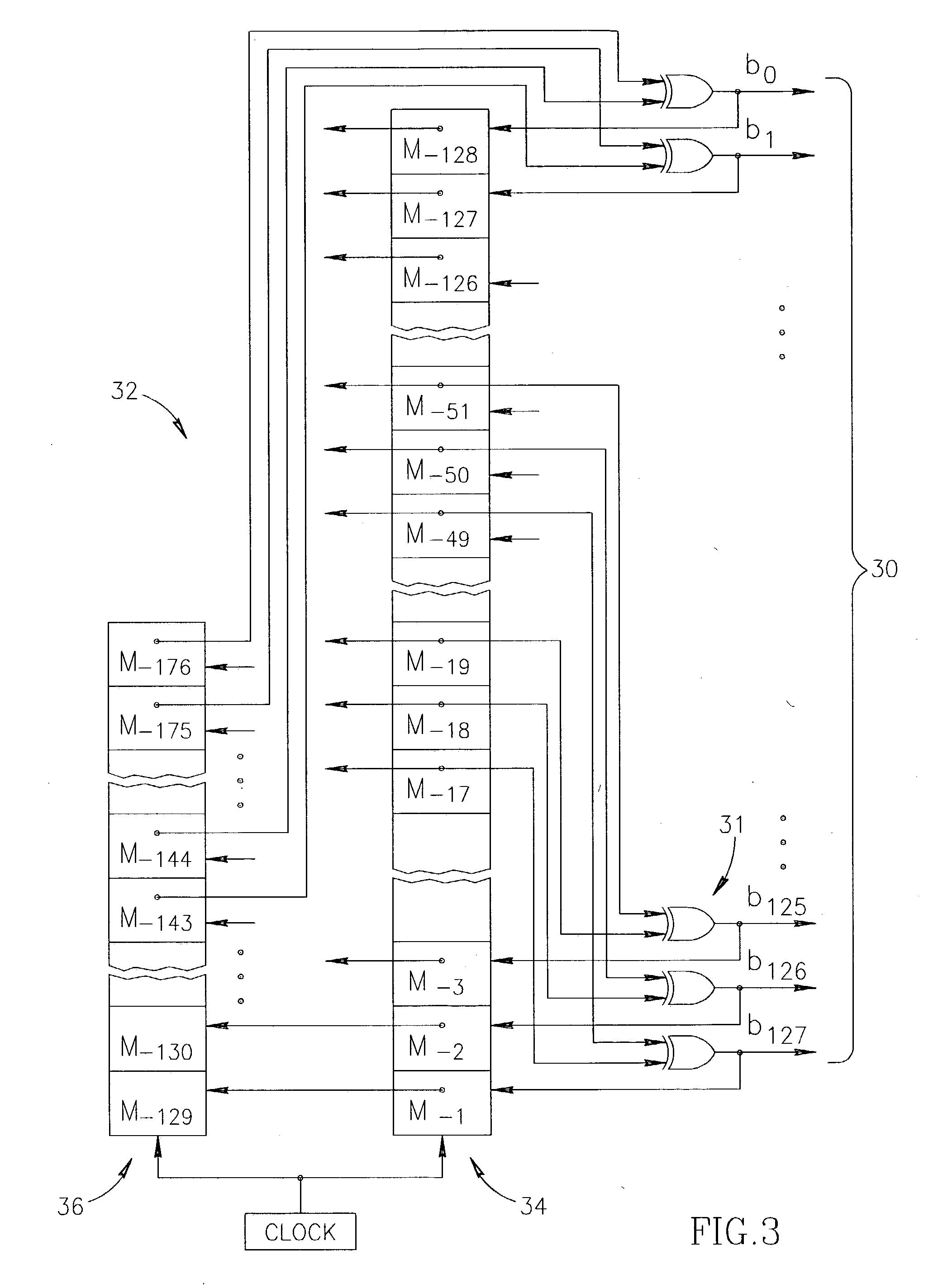
[0023] The Inventors proved a Lemma which allows converting the expression (1) for creating a PRBS pattern based on a given polynomial, into a form which enables avoiding iterative calculations of bits of the PRBS by effectively utilizing the memory.
[0028] However, different "t" values can be selected for calculating different bits of the current PRBS pattern, and that finding can be utilized for minimizing the required memory capacity.
[0039] The Inventors have shown that since different "t" values can be used for calculating different bits of the PRBS, the memory capacity can be further reduced:c'=2.sup.t.sup..sub.m.multidot.n.sub.w-1-2.sup.t.sup..sub.m.sup.-1=c-2.sup-.t.sup..sub.m.sup.-1 (7)

Problems solved by technology

Consequently, if all S positions of a rather long pattern of PRBS sequence is to be created during one and the same generator's clock, this clock would most probably include a considerable number of iterative calculations (and a chain of XORs in the implementation) which means that a high speed clock is hardly achievable for wide buses.
It should be mentioned, however, that the principle of a serial shift register does not allow obtaining a high speed wide bus PRBS generator.

Method used


Image

  • Technique for high speed PRBS generation
  • Technique for high speed PRBS generation
  • Technique for high speed PRBS generation

Examples


Embodiment Construction

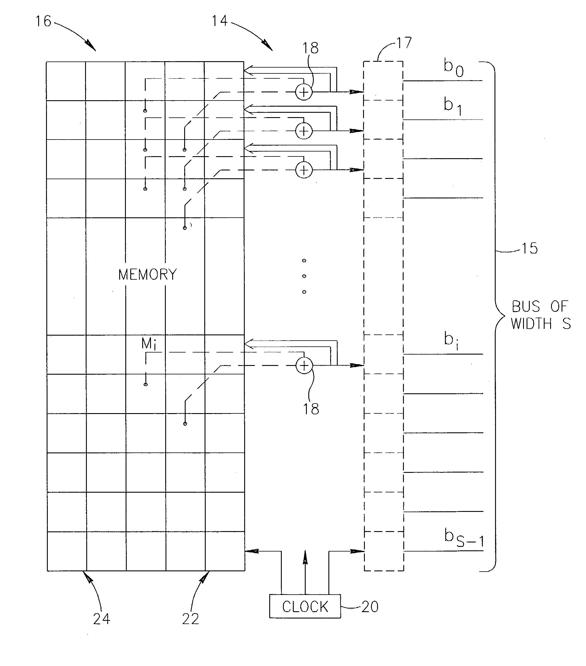
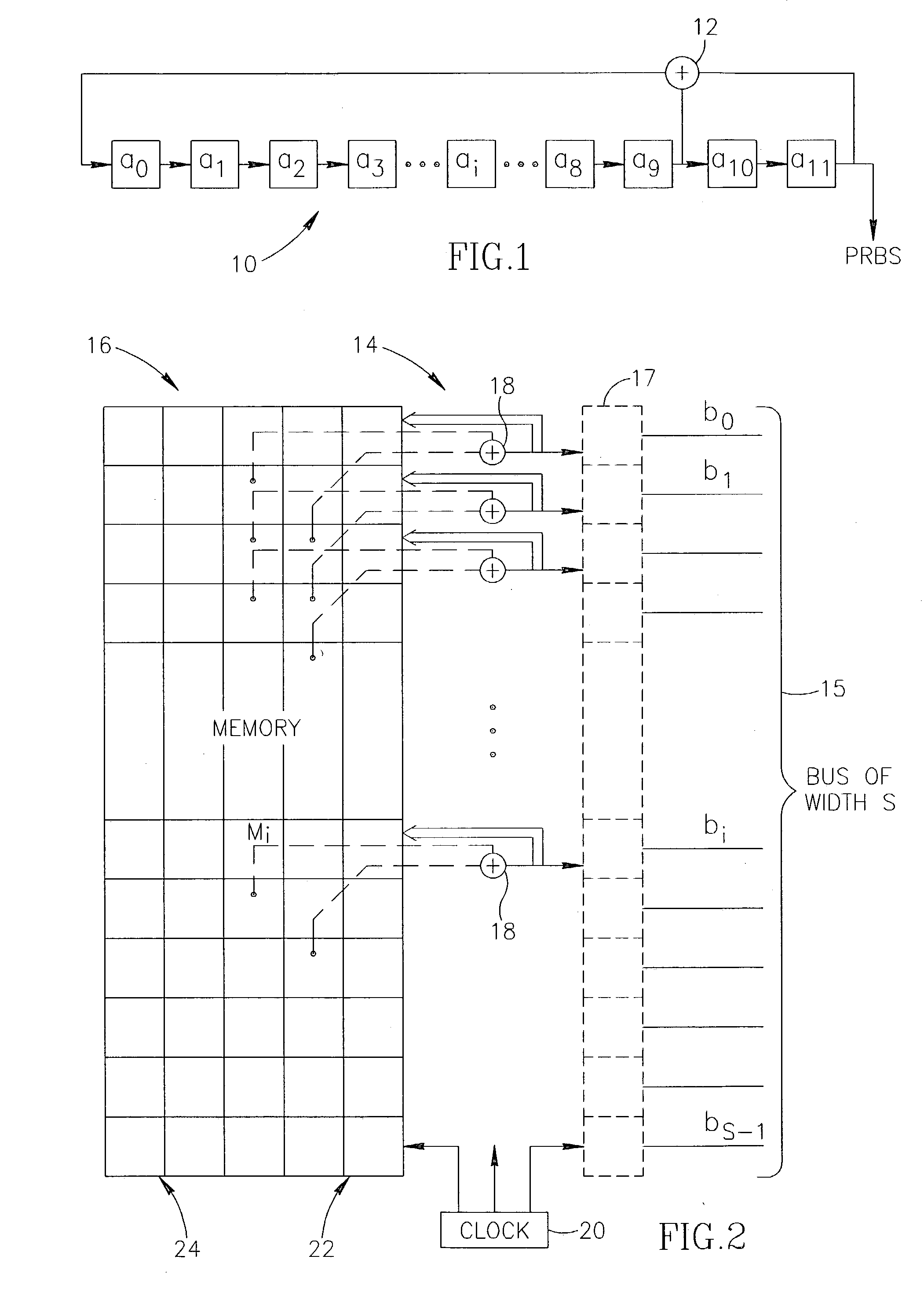
[0045] FIG. 2 illustrates a schematic block-diagram of one embodiment of the PRBS generator 14 according to the invention, which also explains the proposed method.

[0046] The generator 14 comprises a memory 16 and is connected to an S-bit wide bus 15 to create on it a PRBS pattern in the form of a parallel burst of bits. For synchronizing purposes only, a register 17 can be added between the generator and the bus. Each bit of the bus 15 is calculated using the memory 16 and an assembly 18 of logical units performing XOR operations and associated with a particular bit of the bus. There are S such assemblies capable of working in parallel, and they form part of the generator 14. In the drawing, each assembly 18 comprises only one XOR unit; it should be understood that more complex assemblies will be used if a more complex polynomial is given for creating the required PRBS pattern.

[0047] The memory 16 comprises a plurality of registers, capable of performing parallel shift from the top ...


PUM


Abstract

A method and a generator are described for high speed generation of an S-bit long pattern of a PRBS sequence to be periodically burst on to a bus of width S. The technique provides the calculation time being independent from the width S of the bus, and comprises calculation of all S bits of the PRBS pattern separately and in parallel by using previous PRBS patterns stored in a memory. For each bit to be generated, the generator performs a constant number N of logical operations required (by a polynomial defining the PRBS sequence.

Description

[0001] The invention relates to a technique for generating Pseudo Random Binary Sequence (PRBS) for a wide bus (the bus having a large number S of binary positions to be transmitted in parallel), i.e. to a method and a device for periodically creating and transmitting a pseudo-random pattern comprising S bits.[0002] Creation of a PRBS is usually explained and implemented as applying a polynomial to a binary sequence; it can be illustrated by applying a number of XOR (exclusive OR) operations to a binary shift register.[0003] FIG. 1 shows a simple model for PRBS generation illustrating a shift register 10 comprising one XOR unit 12 which performs a logical operation of exclusive OR with the 11.sup.th and 9.sup.th positions of the register to introduce the result in the 0-th position of the register. The output of the register issues a PRBS bit sequence.[0004] The process of forming the bit sequence can be described by the following polynomial having two terms (i.e., w=2, not includin...

Claims


Application Information

Patent Timeline
IPC IPC(8): G06F7/58
CPCG06F2207/582G06F7/584
Inventor RUTHSTEIN, JACOBLITINSKY, LEVSOMMER, RONEN
Owner ECE TELECOM LTD
Learn More