
Rotary drive device

a rotary drive and drive shaft technology, applied in mechanical energy handling, instruments, record information storage, etc., can solve the problems of difficult to fully produce the balancing effect and the noise problem is especially prominen

Inactive Publication Date: 2003-06-26
SANKYO SEIKI MFG CO LTD
View PDF5 Cites 7 Cited by
  • Summary
  • Abstract
  • Description
  • Claims
  • Application Information

AI Technical Summary

Benefits of technology

[0019] In accordance with another embodiment of the present invention, a rotary drive device comprises a plurality of balancing spherical bodies that are attracted to the holding magnet during low speed rotation, including when a rotary body starts, move outward in the radial direction away from the holding magnet by a centrifugal force applied to the plurality of balancing spherical bodies as a result of the rotation of the rotary body, wherein each of the balancing spherical bodies is moved into a position that negates a rotational unbalance of the rotary body to achieve a balancing effect. In one aspect, the balancing spherical bodies are made of a material with little residual magnetism. As a result, the magnetic effect of the holding magnet on the balancing spherical bodies acts consistently at all times regardless of the orientation or posture of the balancing spherical bodies. Consequently, the repulsive force among the plurality of balancing spherical bodies also acts consistently at all times, which effectively prevents noise caused by collisions among the balancing spherical bodies and causes the balancing effect to be achieved even more effectively.
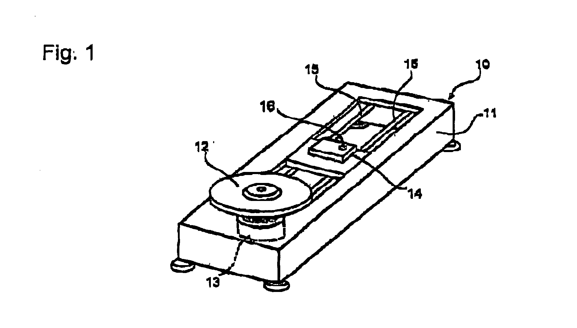
[0021] FIG. 1 is an exterior perspective view of a CD-ROM or DVD drive unit as an example of a device to which the present invention is applied.
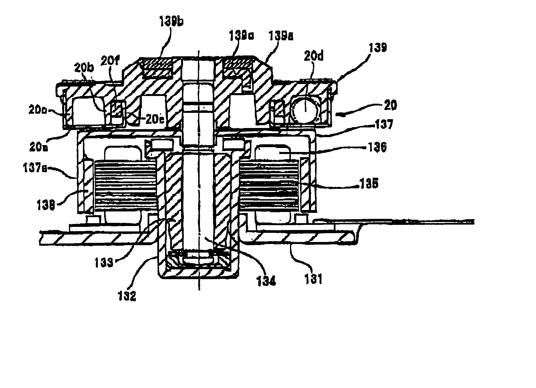
[0022] FIG. 2 is a longitudinal cross section indicating one embodiment of a motor with a self-balancing device used in the CD-ROM or DVD drive unit shown in FIG. 1.

Problems solved by technology

As a result, the plurality of balancing spherical bodies 4 becomes unable to concentrate in a position they should move to in order to resolve an unbalance and instead becomes scattered, which sometimes makes it impossible to fully produce the balancing effect.
Such a noise problem is especially prominent in vertically oriented devices, in which a rotary shaft is horizontal, as shown in FIGS. 7 and 8.

Method used


Image

  • Rotary drive device
  • Rotary drive device
  • Rotary drive device

Examples


Embodiment Construction

[0029] Next, an embodiment of the present invention is described in detail with reference to the accompanying drawings.

[0030] First, the overall structure of a CD-ROM or DVD drive unit to which the present invention is applied is described. On a mechanical chassis 11 of a CD-ROM drive unit 10 shown in FIG. 1, a spindle motor section 13, which rotatably drives a recording disk 12, and an optical pickup device 14, which writes or reads information to and from the recording disk 12 by irradiating a laser beam on it, are mounted. The recording disk 12 is mounted on a disk table (marked 139 in FIG. 2), which is attached to a rotary shaft of the spindle motor section 13.

[0031] The optical pickup device 14 is mounted reciprocativelly on a pair of parallel guide shafts 15, 15 that are attached to the mechanical chassis 11, and the optical pickup device 14 irradiates a luminous flux generated from a laser beam source, omitted from drawings, through an objective lens 16 at the recording disk ...


PUM

PropertyMeasurementUnit
diameteraaaaaaaaaa
speedaaaaaaaaaa
magnetic forceaaaaaaaaaa

Abstract

A rotary drive device includes a plurality of balancing balls that are held to a holding magnet during low speed rotation, including when a rotary body starts. The balancing balls move outward in the radial direction away from the holding magnet by a centrifugal force applied to the plurality of balancing balls as a result of the rotation of the rotary body. Each of the balancing balls is moved into a position that negates a rotational unbalance of the rotary body to achieve a balancing effect. The number of effective revolutions, at which point the plurality of balancing balls that is attracted to the holding magnet begins to move outward in the radial direction away from the holding magnet as the number of revolutions of the rotary body increases, is smaller than the number of resonant revolutions of the rotary body.

Description

[0001] 1. Field of the Invention[0002] The present invention relates to rotary drive devices with a self-balancing mechanism that negates rotational unbalance of rotating bodies.[0003] 2. Related Background Art[0004] In general, various types of rotary drive devices used in industrial machinery, home appliances and computers often make use of self-balancing devices to negate rotational unbalance of a rotary body that includes a rotary shaft. Various structures for self-balancing devices have been proposed. As shown in FIG. 6, one of such self-balancing devices includes a self-balancing mechanism A that includes a hollow circular ring-shaped case 3 attached to a rotary shaft 2, which is an output shaft of a motor section 1, and a plurality of balancing spherical bodies (i.e., balls) 4 housed in a freely movable manner inside the hollow circular ring-shaped case 3.[0005] During low speed rotation including when the motor section 1 starts, each of the balancing spherical bodies 4 is he...

Claims


Application Information

Patent Timeline
Patent Type & Authority Applications(United States)
IPC IPC(8): F16F15/31G11B5/55F16F15/14G11B19/20G11B33/08H02K7/04
CPCG11B33/08G11B5/5582
Inventor UTSUMI, SHINICHIHONDA, ATSUSHI
Owner SANKYO SEIKI MFG CO LTD
Learn More