
System and method for providing equalization in a multiphase communications receiver

Active Publication Date: 2003-06-12
KEYSIGHT TECH
View PDF13 Cites 32 Cited by
  • Summary
  • Abstract
  • Description
  • Claims
  • Application Information

AI Technical Summary

Benefits of technology

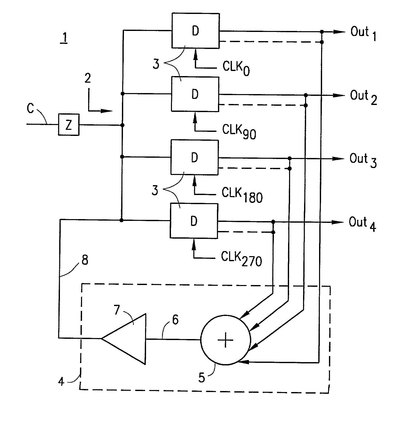
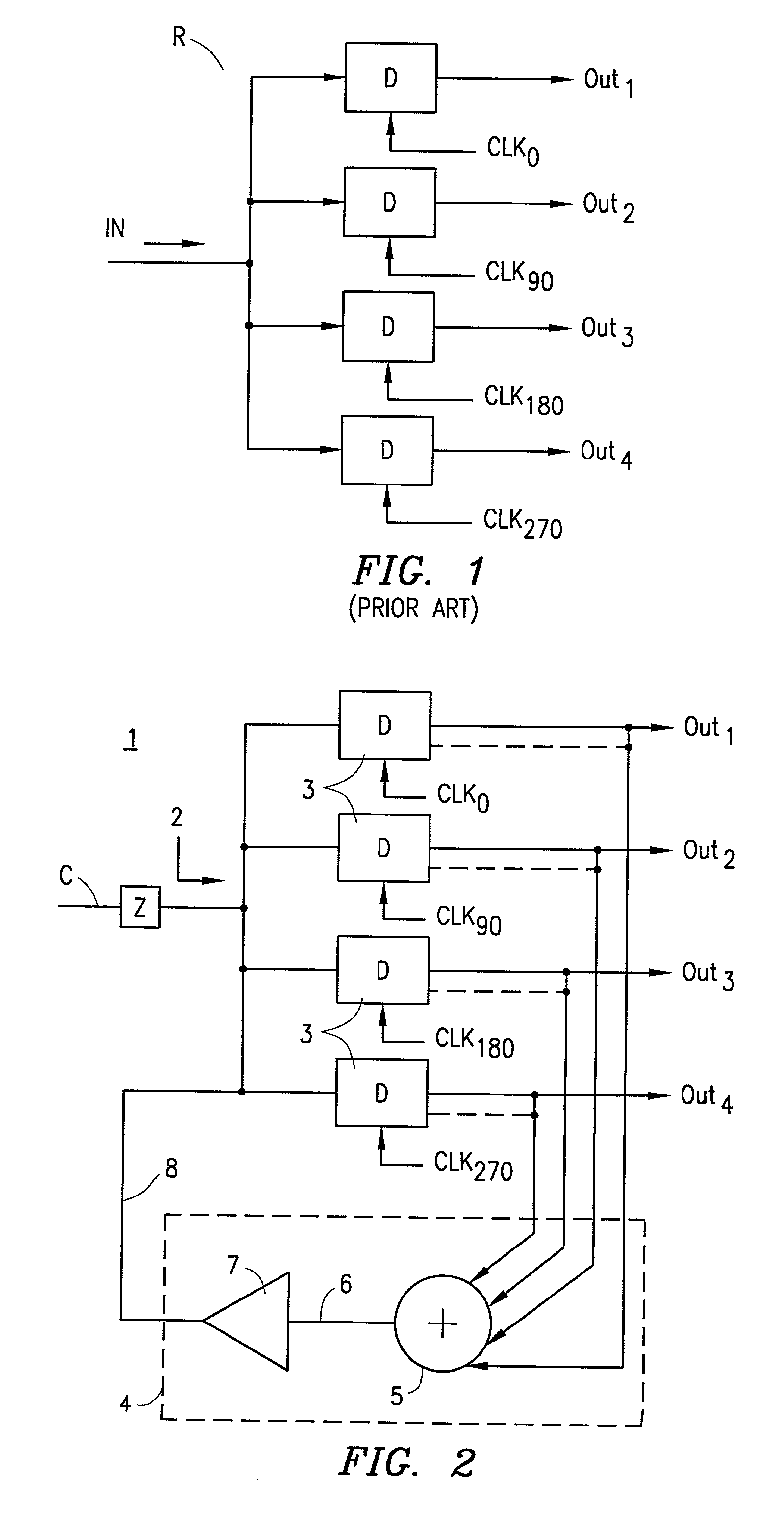
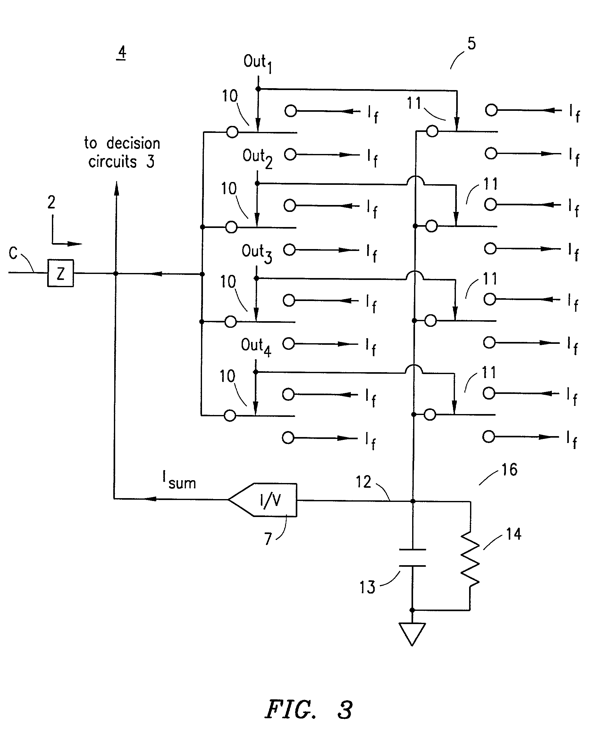
[0011] According to an exemplary embodiment of the present invention, the multiphase receiver includes a plurality of decision circuits. Each decision circuit includes an input connected to a communications channel over which a digital signal is communicated and operates at a frequency that is a fraction of the bit rate of the digital signal. A feedback and / or equalizer circuit receives the output of the decision circuits and applies a feedback signal to the input of the decision circuits that is representative of a combination of the output signals of the decision circuits. The result of this exemplary embodiment is an improved noise margin which increases the capability of correctly interpreting signals communicated over a communications channel having a low-pass frequency characteristic. Because the feedback circuit does not operate at the full bit rate of the received signal, there is less circuit complexity and less demand placed on the receiver.

Problems solved by technology

Because the demands placed on the bandwidth of full bit rate decision circuits, such decision circuits are very difficult to design and implement, especially for high speed operation.
Because single-phase receivers operate at the full bit rate of the received signal, decision feedback circuitry for single-phase receivers are also undesirably required to operate at a higher bandwidth.
Employment of passive filters, either in single-phase or multiphase receivers, is undesirable because the passive filter further attenuates the transmitted signal that has already been attenuated due to channel loss.
The use of active or amplifying filter-type equalizers in multiphase receivers is also undesirable because amplifier circuitry operating at the full bit rate is difficult to achieve using existing technologies.
However, the equalizer is relatively complex and the circuitry therefor may disadvantageously slow the operation of the receiver.

Method used


Image

  • System and method for providing equalization in a multiphase communications receiver
  • System and method for providing equalization in a multiphase communications receiver
  • System and method for providing equalization in a multiphase communications receiver

Examples


Embodiment Construction

[0020] The present invention will now be described more fully hereinafter with reference to the accompanying drawings in which exemplary embodiments of the invention are shown.

[0021] Referring to FIG. 2, there is shown the front end of a receiver 1 for a multiphase communications system. Receiver 1 includes an input 2 connected to a communications channel C over which digital signals are transported. Communications channel C is shown as including a channel source impedance Z associated therewith. Receiver 1 further includes a plurality of decision circuits 3. The input of each decision circuit 3 has an input that is coupled to the communications channel C. Each decision circuit 3 is adapted to determine or sample the state of its input signal at predetermined times, such as in response to a clock signal. Decision circuit 3 may be seen as a comparator circuit responsive to a clock signal so as to periodically determine the state of the input signal of the decision circuit 3.

[0022] De...


PUM


Abstract

A circuit and method for receiving digital signals are disclosed. The circuit includes an input connected to a communications channel over which a digital signal is communicated and operates a plurality of multiple decision circuits at a frequency that is a fraction of the bit rate of the digital signal. A feedback and / or equalizer circuit receives the output of the decision circuits and applies a feedback signal to the input of the decision circuits that is representative of a combination of output signals of the decision circuits. The result is seen to improve the noise margin for correctly interpreting signals communicated over a communications channel having a low-pass characteristic.

Description

[0001] 1. Technical Field of the Invention[0002] The present invention relates to receivers for communications systems, and particularly to providing equalization to multiphase receivers in communications systems.[0003] 2. Description of Related Art[0004] Receivers for handling information transported over a communications link generally fall into any of a number of different categories. In a single-phase communications receiver, a single decision circuit operates at the fill bit rate of the received signal in order to determine the state of each bit therein. Because the demands placed on the bandwidth of full bit rate decision circuits, such decision circuits are very difficult to design and implement, especially for high speed operation.[0005] A multiphase communications receiver utilizes a plurality of decision circuits to determine the state of received signals. As shown in FIG. 1, the decision circuits D of a conventional multiphase communications receiver R sample the received...

Claims


Application Information

Patent Timeline
IPC IPC(8): H04L25/03H04L25/06
CPCH04L25/03146H04L2025/0349H04L25/061
Inventor STEINBACH, GUNTER W.
Owner KEYSIGHT TECH
Learn More