
Convection blood warming system with disposable flattened tube envelope incorporating paperboard needle for inserting envelope between heating plates and employing active and passive insulation of outlet flow path to provide normothermic fluid at zero to 600 milliliters per minute

Inactive Publication Date: 2003-05-29
BAKKE ALLAN P
View PDF0 Cites 18 Cited by
  • Summary
  • Abstract
  • Description
  • Claims
  • Application Information

AI Technical Summary

Benefits of technology

[0011] A new means of loading the flexible, floppy flattened envelope heat exchanger into the blood warmer apparatus is simple and economical, employing a paperboard inserter that passes easily through the very narrow slot between the two heating plates and then is grasped at the opposite end of the blood warmer and used to pull the envelope heat exchanger into place. This inserter eliminates the more complex stiff plastic cassette often used currently, and also allows closer spacing of the heating plates, resulting in more efficient heat transfer.
[0012] At low flow rates, blood cools by convection as it flows to the patient, negating the value of the blood warmer apparatus. The conductively warmed and externally insulated drip chamber holder of this invention in synergy and complementary action with a patient intravenous line that is insulated by an annular air space co-extruded with the central blood tube significantly reduce convective heat loss to the cooler ambient air. An optionally employed, temperature-controlled, reusable external heater may be applied to the distal portion of the patient line, allowing delivery of normothermic intravenous fluid to the patient at very low flow rates, down to essentially zero flow rate.
[0014] Accordingly, several objects and advantages of my invention are as follows. The present invention employs a thin semi-rigid paperboard inserter to load the flattened plastic envelope disposable heat exchanger between the fixedly mounted parallel heating plates which are closely spaced apart. Use of this inserter in place of a rigid plastic cassette to carry the disposable envelope allows the heating plates to be closer together, resulting in higher efficiency heat transfer.
[0015] A further object of the present invention is to allow delivery of warm fluid at low flow rates to the patient. Advantages working together in synergy to produce this result are the use of a heat conductive drip chamber holder sleeve closely attached to one of the heating plates to keep the drip chamber warm, and a flexible plastic patient line i.v. tubing with larger outside tubing extruded as part of the patient line. An annular air gap between the outer and inner tubes passively insulates the i.v. line from the cooler ambient air. Also, an optionally employed reusable external sensorless or sensor-controlled electric heater applied to the distal portion of the patient line actively warms fluid just before delivery to the patient at very low flow rates. These three improvements acting together in synergistic complementary action provide improvements in low flow performance not achieved before.
[0016] Another object of the present invention is to automatically vent high flow rates of air or bubbles from the flow path before infusion of fluid into the patient. It is well-known that infusion of air or gas into the veins of a patient may be lethal. In the present invention, a large (about 1 inch in diameter) hydrophobic vent is incorporated into the top of the drip chamber, capable of venting large volumes of air quickly. A commercially available check valve prevents reverse flow of air into the fluid flow path.

Problems solved by technology

U.S. Pat. No. 5,875,282 employs a flat envelope heat exchanger carried into position by a rigid plastic cassette and warms the heating plates directly with resistance heaters, but is less effective at high and low flow rates.
The warm water flows toward the patient in one half of the annular lumen, turns around 180 degrees and returns to the blood warmer, actively warming the intravenous fluid, but is only effective at low flow rates.
It is well-known that infusion of air or gas into the veins of a patient may be lethal.

Method used


Image

  • Convection blood warming system with disposable flattened tube envelope incorporating paperboard needle for inserting envelope between heating plates and employing active and passive insulation of outlet flow path to provide normothermic fluid at zero to 600 milliliters per minute
  • Convection blood warming system with disposable flattened tube envelope incorporating paperboard needle for inserting envelope between heating plates and employing active and passive insulation of outlet flow path to provide normothermic fluid at zero to 600 milliliters per minute
  • Convection blood warming system with disposable flattened tube envelope incorporating paperboard needle for inserting envelope between heating plates and employing active and passive insulation of outlet flow path to provide normothermic fluid at zero to 600 milliliters per minute

Examples


Embodiment Construction

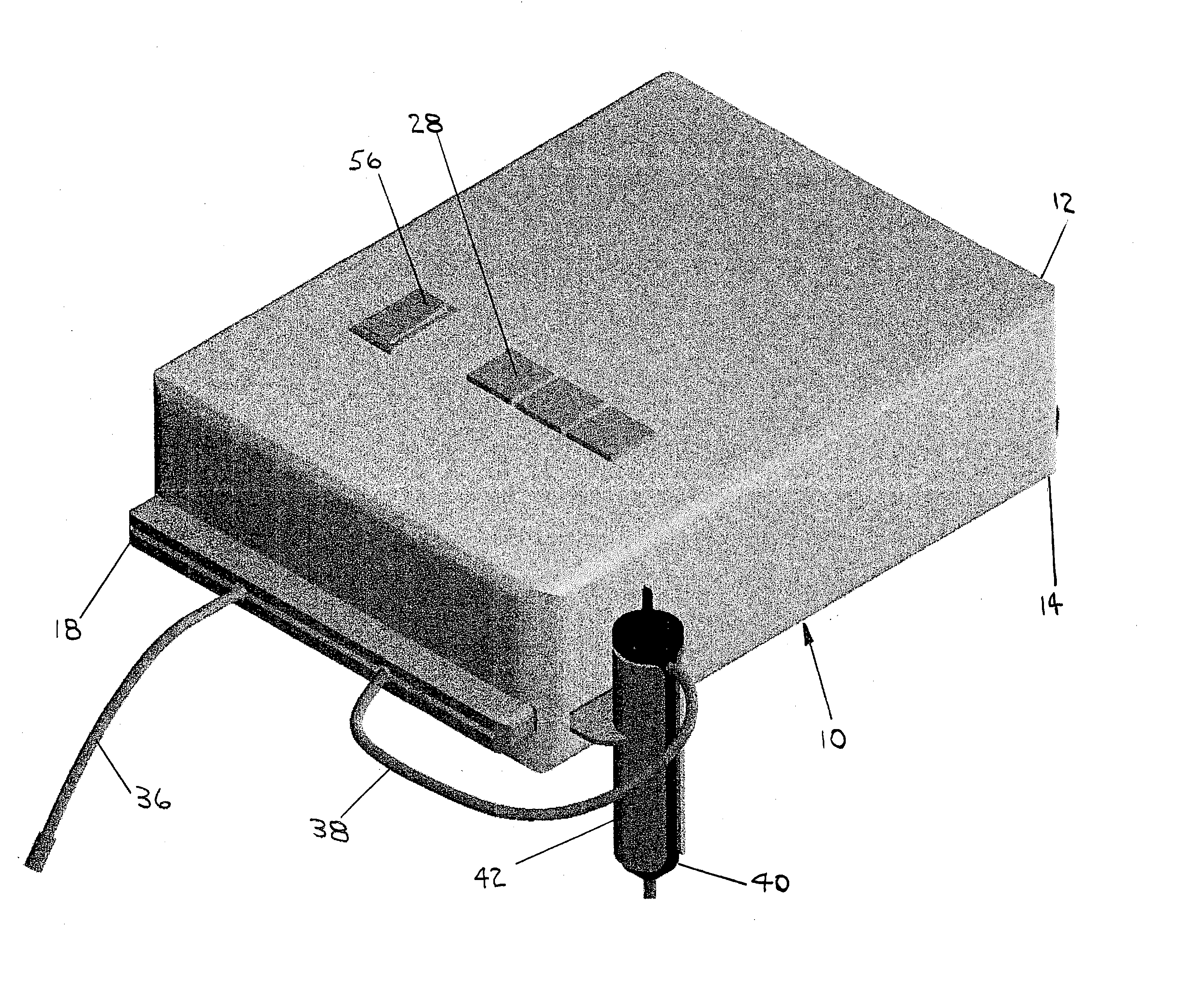
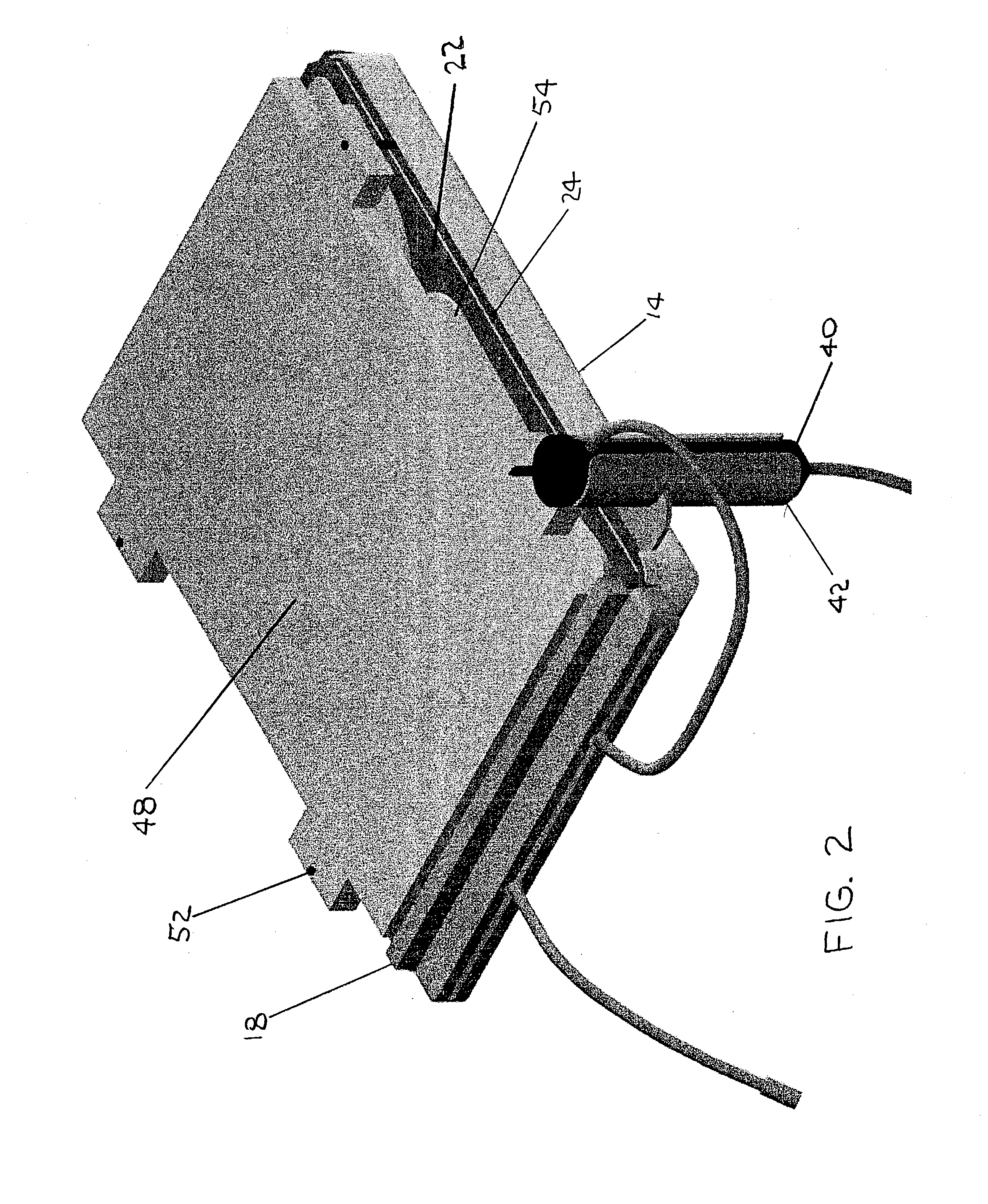
[0053] FIG. 1 shows the present blood warmer invention 10 with front case 12 and rear case 14 made from commercially available aluminum box enclosures about 0.06 inch thick. Disposable heat exchanging blood warming envelope 16 passes through inserter guide 18. Disposable heat exchanging blood warming envelope 16 lies between front heat transfer plate 22 and rear heat transfer plate 24 and is hidden from view in this drawing. Paperboard inserter 26 is attached to the rightmost end of disposable heat exchanging blood warming envelope 16 (FIG. 4), and is used to insert disposable heat exchanging blood warming envelope 16 between front heat transfer plate 22 and rear heat transfer plate 24, pulling it into operating position like a needle pulls thread.

[0054] Temperature controller 28 is seen protruding through front case 12 and is activated by power switch 56. Thermistor inputs from several locations on front heat transfer plate 22 and rear heat transfer plate 24 allow close temperature...


PUM


Abstract

A thin, flat paperboard inserter or "needle" which is longer than the blood warmer heating plates is attached to the edge of the flattened tube envelope to enter the very narrow gap between the heating plates. The inserter is fed between the heating plates and advanced to emerge from the other end of the blood warmer where it is grasped and used to pull the envelope into operational position. A high air flow hydrophobic vent with check valve to prevent reverse flow is incorporated into the drip chamber to allow automatic priming and venting of air bubbles. A conductively heated and externally insulated drip chamber holder and a patient intravenous line that is passively insulated by a small annular air space extruded as part of the tube preserve heat in the warmed fluid, improving low flow rate performance. A reusable external heater may optionally be applied to the distal portion of the patient line to provide normothermic fluid to the patient down to essentially zero flow rate.

Description

[0001] The present invention relates to my two previous inventions U.S. Pat. Nos. 5,013,889 and 5,420,962. The present invention continues to use heating by vapor condensation employing flat plate heat pipes to warm blood through the walls of a thin plastic envelope heat exchanger. The improvements of this invention are applicable to other blood warmers not employing vapor condensation heating but which use resistively heated flat plate warming.[0002] The present invention relates to delivering warm fluid to a patient at low flow rates, all the way down to essentially zero flow rate, providing fluid at 37 degrees C. leaving the patient line i.v. tubing 6 ft from the blood warmer outlet. This results in over-all warmer performance which delivers fluid warmed to at least 35 C. from zero to 600 ml / min when entering fluid is 10 C.[0003] The present invention also relates to my Provisional Patent Application No. 60 / 335,862, Convective Blood Warming System with Disposable Flattened Tube E...

Claims


Application Information

Patent Timeline
IPC IPC(8): A61M5/44H05B3/58
CPCA61M5/44A61M5/445H05B3/58A61M2205/3653A61M2205/3633
Inventor BAKKE, ALLAN P.
Owner BAKKE ALLAN P
Learn More