Method for producing a sequence of high-voltage ignition sparks and high-voltage ignition device

a high-voltage ignition and high-voltage technology, which is applied in the direction of mechanical equipment, machines/engines, lighting and heating apparatus, etc., can solve the problems of increasing the material expenditure of the ignition system, and the relative long time between the charging and discharging operation of the ignition storage devi

Inactive Publication Date: 2003-05-15
ROBERT BOSCH GMBH
View PDF7 Cites 24 Cited by
  • Summary
  • Abstract
  • Description
  • Claims
  • Application Information

AI Technical Summary

Benefits of technology

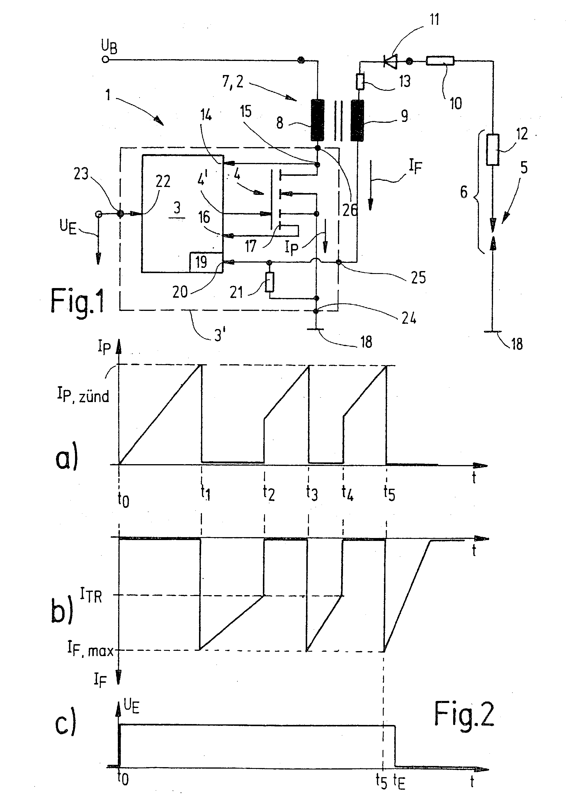
[0003] Using the method of generating a sequence of high-voltage ignition pulses having the features of claim 1 and using the high-voltage ignition device having the features of claim 8, it is possible in an advantageous manner to shorten the time between a discharging operation and a charging operation of an ignition energy storage device. This makes it possible to provide multiple high-voltage ignition sparks during one ignition cycle. However, it is also possible to reduce the capacitance of the ignition energy storage device due to the increase in the number of ignition sparks, i.e., for example, it is possible to use a smaller ignition coil in comparison with the related art. Essentially the shortening of the recharging time of the ignition energy storage device is achieved by recharging it before it is completely discharged. Thus, there remains a certain residual ignition energy in the ignition energy storage device, regardless of changes in such parameters as ignition voltage, operating voltage of the ignition spark, rotational speed of the internal combustion engine, ratio of the air-fuel mixture, battery voltage situation or the like, so that the recharging operation is shortened whereupon subsequent sparks may be generated at a much shorter interval after the first spark.[0004] To prevent the ignition energy storage device from discharging completely by a simple method, in a refinement of the present invention, the ignition spark current is measured (while the ignition spark is burning) and when the ignition spark current drops below a specifiable value, the recharging operation of the ignition energy storage device is started. To prevent uncontrolled re-ignition on the ignition spark generating means which may be caused by current peaks in the ignition spark current, for example, in an especially preferred embodiment the recharging operation of the ignition energy storage device is started only when the ignition spark current has dropped below the specifiable value for a specified period of time. This also guarantees, however, a minimum spark duration, which will be necessary for ignition of the air-fuel mixture in the combustion chamber. Since restarting takes place only when the ignition spark current drops below the specifiable value, the short recharging time of the ignition spark storage device is also reached because residual ignition energy is available in the storage device.[0005] If a measuring lead is provided from the ignition energy storage device to a control unit for an ionic current measurement, this measuring lead may be used to measure the ignition spark current. This also yields an inexpensive and robust implementation of control of the recharging operation by the control unit.[0006] Additional advantageous embodiments are derived from the subclaims.

Problems solved by technology

One disadvantage of the known multiple-spark systems is that there is a relatively long period of time between a charging and discharging operation of the ignition storage device.
In addition, a greater material expenditure is necessary for ignition systems having multiple ignition energy storage devices.

Method used


Image

  • Method for producing a sequence of high-voltage ignition sparks and high-voltage ignition device
  • Method for producing a sequence of high-voltage ignition sparks and high-voltage ignition device
  • Method for producing a sequence of high-voltage ignition sparks and high-voltage ignition device

Examples


Embodiment Construction

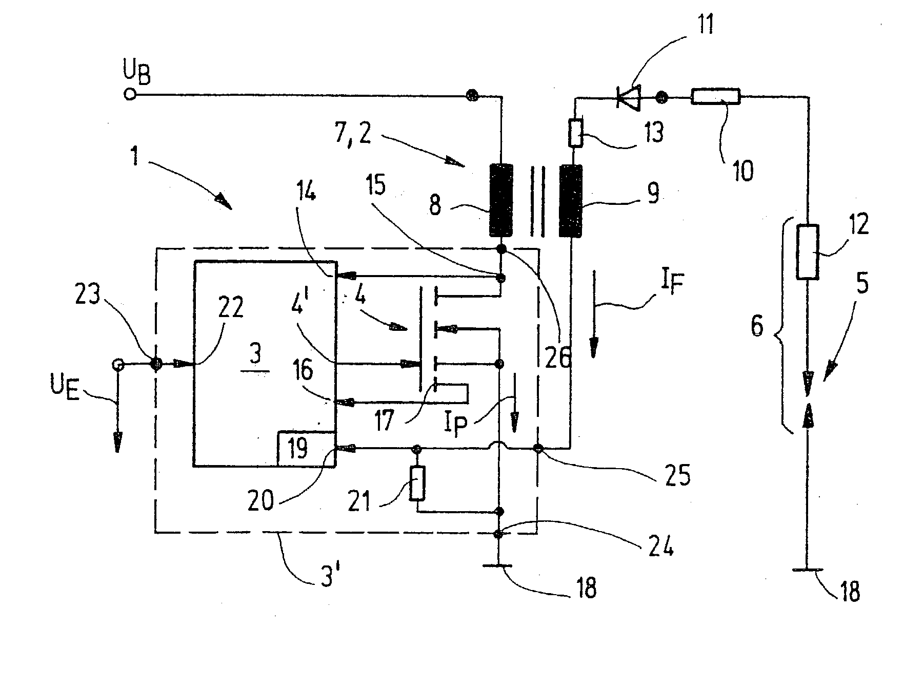
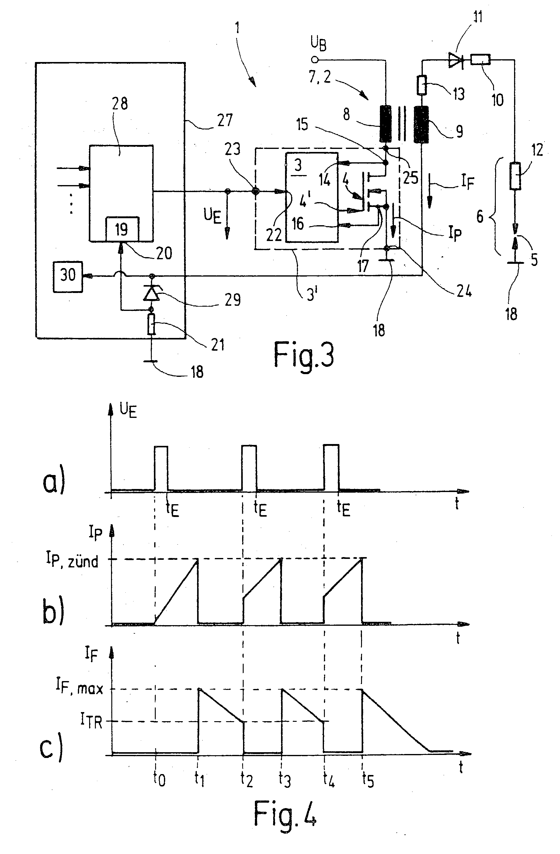
[0012] FIG. 1 shows a high-voltage ignition device 1 including an ignition energy storage device 2, a control unit 3 and a switching element 4. High-voltage ignition device 1 supplies electric power to a spark gap 5 to generate a high-voltage ignition spark. Spark gap 5 is formed on an ignition spark generating means 6, which may preferably be implemented as a spark plug.

[0013] In a preferred embodiment, ignition energy storage device 2 is designed as an inductor, i.e., as ignition coil 7 having a primary winding 8 and a secondary winding 9. Ignition spark generating means 6 is connected to secondary winding 9, an interference-suppression resistor 10 and a spark suppression diode 11 are also situated in this circuit, the anode being connected to spark gap 5 and the cathode being connected to secondary winding 9. Furthermore, bum-off resistor 12 of ignition spark generating means 6 and resistor 13 of ignition energy storage device 2 are also shown in this circuit. At one of its ends,...


PUM


Abstract

A method of generating a sequence of high-voltage ignition sparks is described, wherein an ignition energy storage device (2) is charged up to a specifiable charge state (IP, ZÜND), by a discharge of the ignition energy storage device (2), a spark is generated on an ignition spark generating means (6) connected to the ignition energy storage device (2), a recharging operation of the ignition energy storage device (2) is started before the ignition energy storage device (2) is completely discharged, and by discharging the ignition energy storage device (2), an additional ignition spark is generated on the ignition spark generating means (6).

Description

[0001] The present invention relates to a method of generating a sequence of high-voltage ignition pulses and a high-voltage ignition device according to the preamble of claim 8.BACKGROUND INFORMATION[0002] Various high-voltage ignition devices are known in the related art. In addition to inductive ignition, known systems also include capacitive ignition systems and a.c. ignition systems. Furthermore, there are known ignition systems in the related art in which a sequence of high-voltage ignition sparks is generated. This device, which is also known as double ignition, generates multiple ignition sparks during one combustion cycle in a cylinder in order to improve combustion. For this purpose, for example, there are known ignition systems having multiple ignition energy storage devices, e.g., ignition coils. The ignition spark sequence is controlled in time in the related art, this time control being implemented through software and / or hardware using a control unit. One disadvantage...

Claims


Application Information

Patent Timeline
IPC IPC(8): F02P15/10F02P3/04F02P17/12F23Q3/00
CPCF02P15/10F23Q3/004F02P17/12
Inventor VOGEL, MANFREDHERDEN, WERNER
Owner ROBERT BOSCH GMBH
Why Eureka
Try Eureka