Cooling apparatus boiling and condensing refrigerant with improved tunnel structure
a technology of condensing refrigerant and cooling apparatus, which is applied in the direction of semiconductor/solid-state device details, lighting and heating apparatus, etc., can solve the problems of cost disadvantage, difficulty in manufacturing it,
- Summary
- Abstract
- Description
- Claims
- Application Information
AI Technical Summary
Problems solved by technology
Method used
Image
Examples
second embodiment
[0108] Second Embodiment
[0109] FIG. 5 shows plan views of the plates 5A, 5C and 5D.
[0110] The present embodiment is an example case in which the shapes of the openings provided in the first intermediate plate 5C and the second intermediate plate 5D are made substantially similar and may be, for example, circles (or polygons such as triangles or quadrilaterals) as shown in FIG. 5.
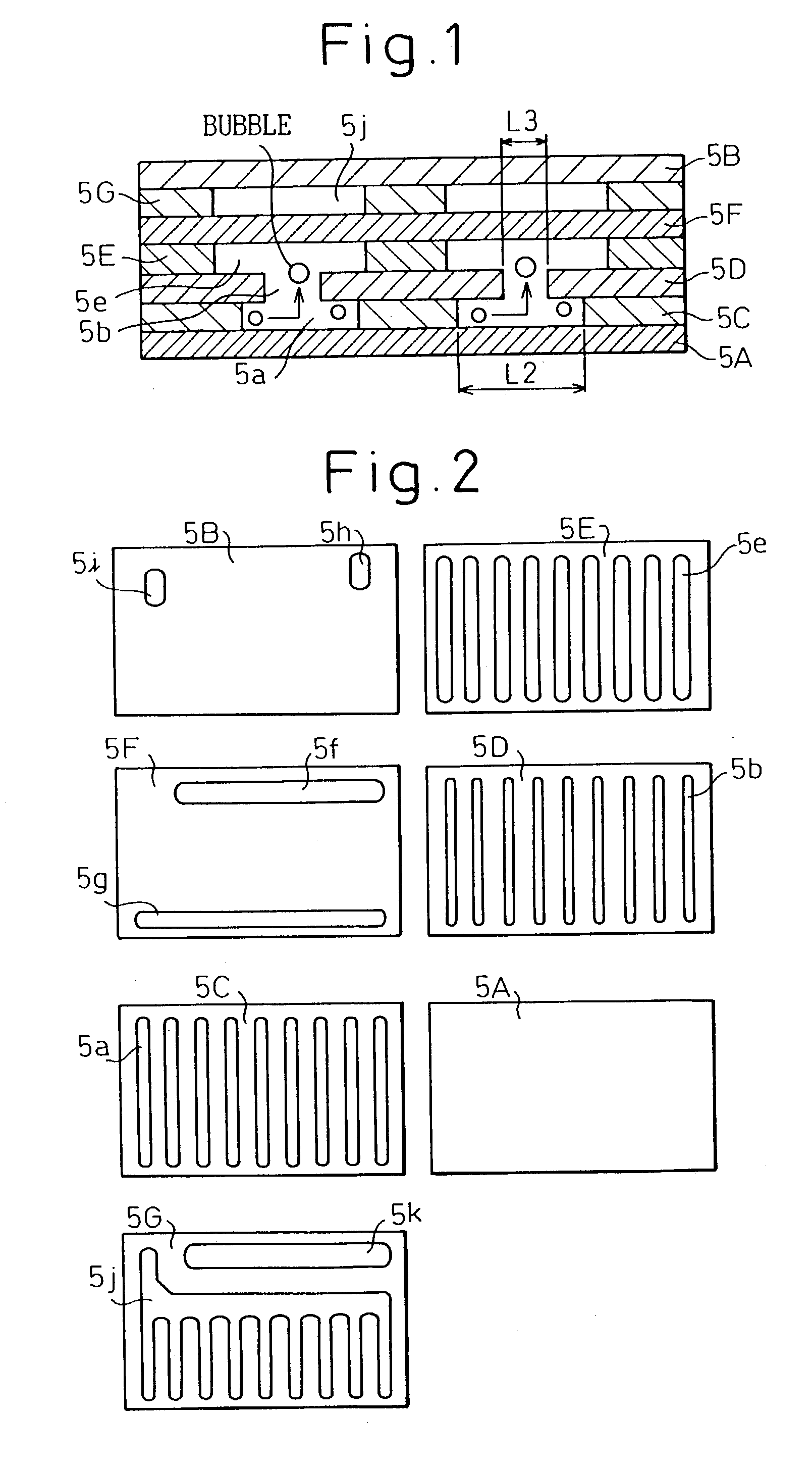
[0111] In this case also, the opening width (diameter of the opening) of the first opening 5a in the first intermediate plate 5C is wider than that of the second opening 5b in the second intermediate plate 5D, and if both the intermediate plates 5C and 5D are stacked, the first opening 5a and the second opening 5b are arranged concentrically as shown in FIG. 6, a tunnel structure (refer to FIG. 1) can be formed, and the same effects as those in the first embodiment can be obtained.
third embodiment
[0112] Third Embodiment
[0113] FIG. 7 shows plan views of the plates 5A, 5C and 5D.
[0114] The present embodiment is an example case in which a large first opening 5a in the first intermediate plate 5C is provided so as to occupy substantially all the surface of the plate, as shown in FIG. 7.
[0115] In this case, if the first intermediate plate 5C and the second intermediate plate 5D are stacked, the length L2 of the tunnel portion becomes equal to the dimension L1 (dimension between the neighboring second openings 5b) of the metal portion 5c of the second intermediate plate 5D, as shown in FIG. 8. If, therefore, the dimension L1 of the metal portion 5c is designed so as to be large, a tunnel structure the length of the tunnel portion of which is long can be formed and higher performance can be achieved because the formation of the thin liquid film on the boiling surface is promoted.
fourth embodiment
[0116] Fourth Embodiment
[0117] FIG. 9 shows plan views of the plates 5A, 5C and 5D.
[0118] The present embodiment is an example case in which first openings 5a in the first intermediate plate 5C are formed so as to be elongate slit-shaped, and the opening dimension of the second openings 5b to be provided in the second intermediate plate 5D are made smaller than the opening dimension of the first openings 5a in the longitudinal direction (in the vertical direction in FIG. 9), as shown in FIG. 9.
[0119] In this case, if the first intermediate plate 5C and the second intermediate plate 5D are stacked, the plural second openings 5b communicate with the first openings 5a in the longitudinal direction, as shown in FIG. 10. Because of this, it is found that a tunnel structure, the length L2 of the tunnel portion of which is long, can be formed when the sectional view of the first opening 5a in the longitudinal direction is viewed as shown in FIG. 8, therefore higher performance can be achie...
PUM
 Abstract
Description
Claims
Application Information
 - R&D
- Intellectual Property
- Life Sciences
- Materials
- Tech Scout
- Unparalleled Data Quality
- Higher Quality Content
- 60% Fewer Hallucinations
Browse by: Latest US Patents, China's latest patents, Technical Efficacy Thesaurus, Application Domain, Technology Topic, Popular Technical Reports.
© 2025 PatSnap. All rights reserved.Legal|Privacy policy|Modern Slavery Act Transparency Statement|Sitemap|About US| Contact US: help@patsnap.com


