
Computer and method providing for illumination of keyboard

Inactive Publication Date: 2003-02-27
LENOVO (SINGAPORE) PTE LTD
View PDF3 Cites 16 Cited by
  • Summary
  • Abstract
  • Description
  • Claims
  • Application Information

AI Technical Summary

Benefits of technology

[0007] In order to attain these objects, a light accumulator is employed for the characters and symbols on each key top to avoid the problems associated with the more conventional solution of providing an external light source. More specifically, the character, symbol or the like is printed out with use of a light accumulator so that light energy is accumulated in the light accumulator while the key is being used in locations having sufficient ambient light. Thereby, when the key is used in a darkened environment, the light accumulator emits the character, symbol, or the like so that the user can recognize the character / symbol.
[0008] The method that prints out characters and symbols on key tops with use of such the light accumulators is less expensive than the above-described conventional technique that provides a keyboard with a light source that lights up the keyboard. It also avoids any increase in the workload for assembling the lap-top PC. The light accumulating material adds no measurable weight to the PC and, finally, since the light is emitted from the light accumulator on the key top itself, there is no problem with uneven lighting or shadows.
[0009] One problem that arises when using light accumulating material on the key tops is providing a coating of light accumulator thick enough to provide a satisfactory emission performance. The emission performance means a measurement of the emission brightness after a light irradiation for light accumulation and / or a measurement of the emission brightness recognized in a predetermined time. The emission performance, when the light-accumulation coating is the same, is proportional to the thickness of the light accumulator per unit area. Consequently, as the light accumulator increases in thickness, the emission performance improves. At a sufficient thickness, the emission performance is satisfactory for continuous operation of the PC in a dark place.
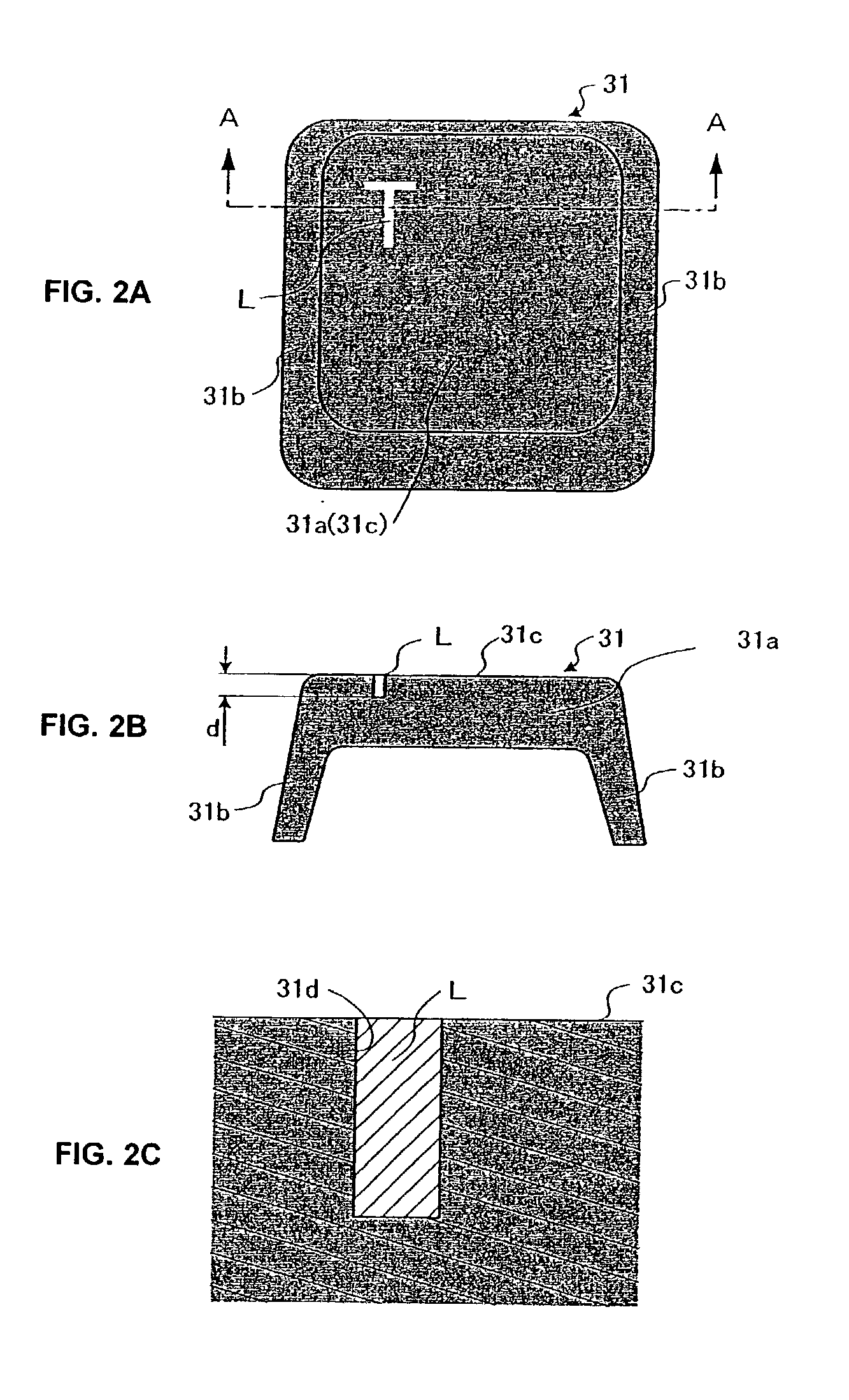
[0011] In order to solve the above-mentioned problems, the present invention proposes a method that forms a groove in each key top in accordance with the shape of the key"s respective character or symbol and dispose a light accumulator in the groove at a thickness that can assure the predetermined emission performance necessary for satisfactory performance. Because the light accumulator is disposed in such a groove, the light accumulator is not worn out nor comes off even when the user continues the operation of the key. The shape of the groove for embedding the light accumulator therein such way can be varied. For example, it is possible to use the groove to form an area denoting a character / symbol or to place the groove along the frame of such an area for denoting the character / symbol. It is also possible to form a groove so as to surround such an area for denoting the character / symbol. According to the present invention, a groove formed in accordance with the shape of a character / symbol means a concept that includes all of these groove forming methods and any others whereby the groove with its applied light accumulator indicates to the use the identity of the key"s respective character / symbol.
[0023] Furthermore, it is still another object of the present invention to provide a keyboard preferred for the above-described computer. The keyboard includes a plurality of operation keys disposed thereon. Each of those operation keys has a key body having a key top surface and a character / symbol display member recognized on the key top surface. The display member is composed of a light accumulator that can keep a residual emission brightness of at least 50 mcd / m2 for 30 minutes after the light accumulator is exposed to a 400-lux light from a D65 standard light source for 20 minutes. The display meter composed as described above can assure enough visibility for the characters / symbols during continuous operation of the lap-top PC in a dark place. Such a display meter composed of a light accumulator must be formed so as not to be protruded from the key top surface on the keyboard of the present invention. This is to prevent the light accumulator from coming off due to the operation of the user.

Problems solved by technology

One problem that arises when using light accumulating material on the key tops is providing a coating of light accumulator thick enough to provide a satisfactory emission performance.
Another problem that arises is that, sometimes, it is difficult to maintain emission performance from a light accumulator even when the thickness should be sufficient, since the light accumulator coating on the key top is worn out as~the user operates the key.

Method used


Image

  • Computer and method providing for illumination of keyboard
  • Computer and method providing for illumination of keyboard
  • Computer and method providing for illumination of keyboard

Examples


Embodiment Construction

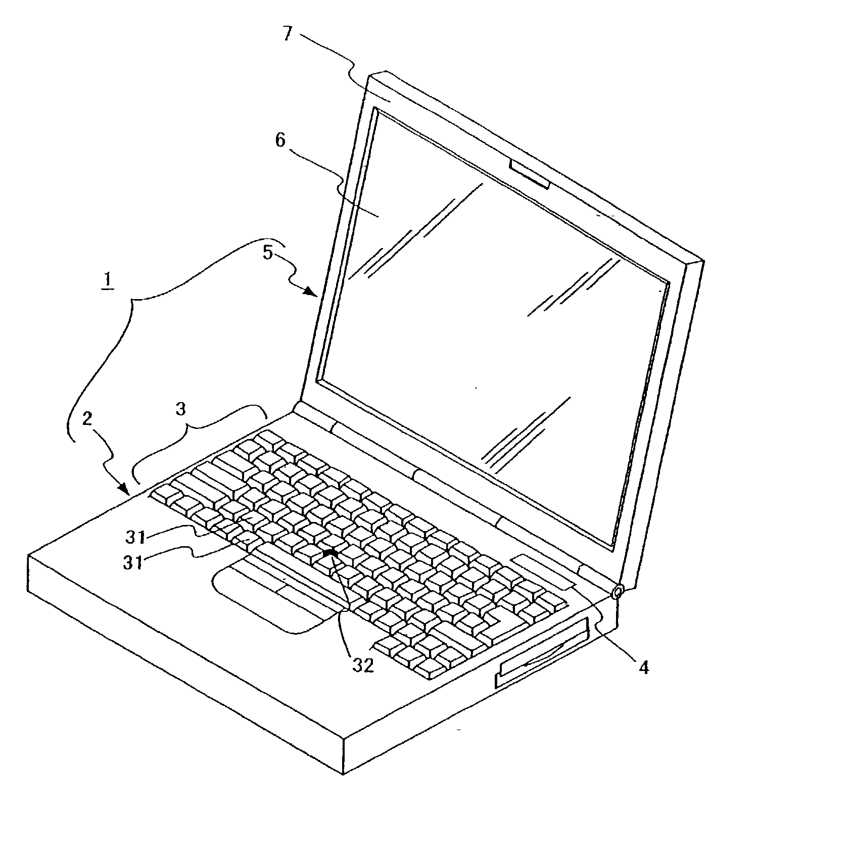
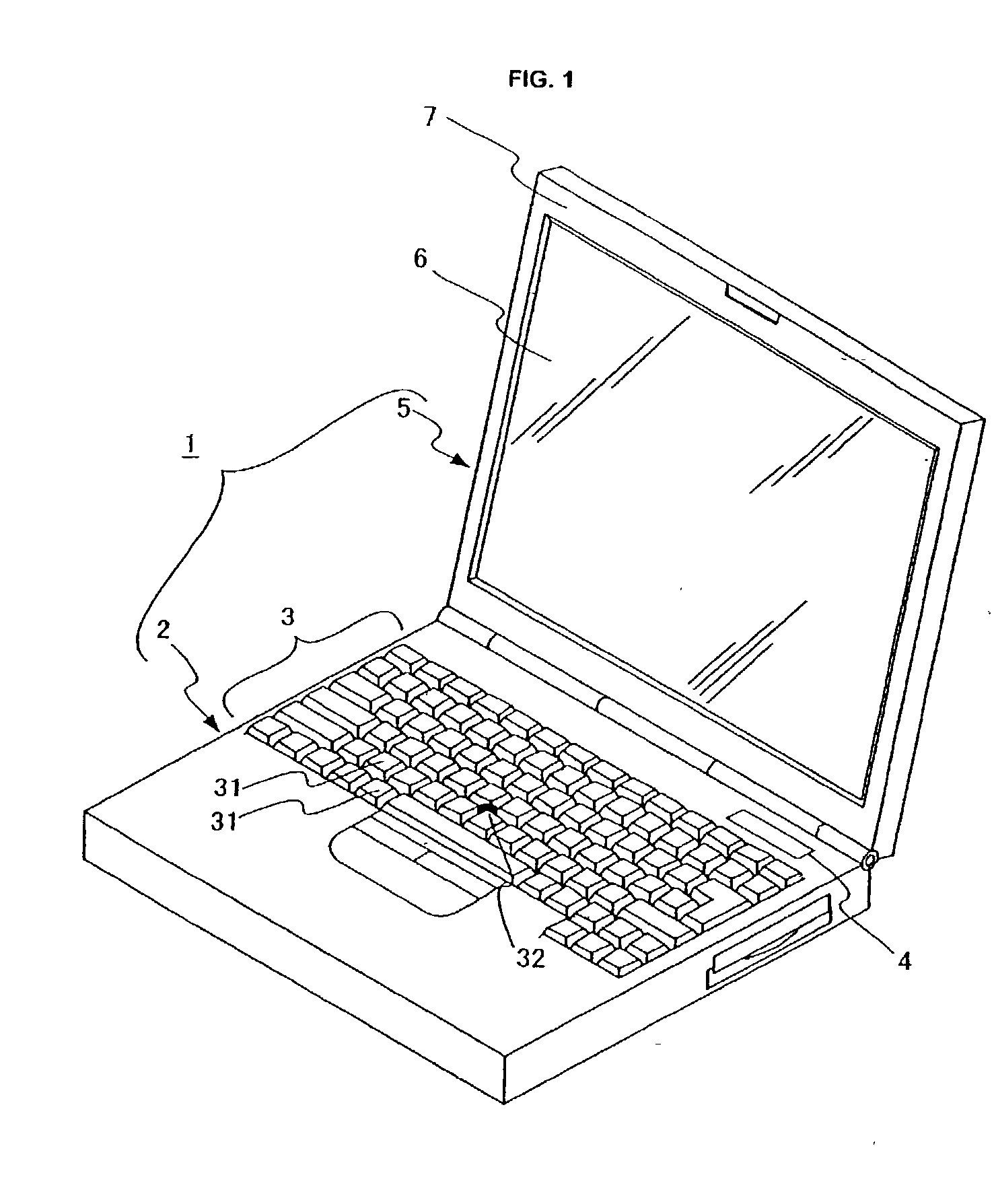
[0047] As shown in FIG. 1, the lap-top PC 1 is composed of a main body 2 and a liquid crystal display 5. The main body 2 and the liquid crystal display 5 are connected to each other by hinges (not shown) so that the liquid crystal display 5 can be opened from / closed to the main body 2.

[0048] The main body 2 is provided with a keyboard 3 used as input operation means. This keyboard 3 is composed of a plurality of keys 31 used to enter characters, symbols, etc., as well as to control various operations of the lap-top PC 1. On the keyboard 3 is also disposed a pointing device 32. The lap-top PC 1 may also include other types of pointing devices such as touch pads, joysticks, etc. (not shown). In the main body 2 is disposed a built-in battery (not shown) used to drive the lap-top PC 1. A residual emission level meter 4 is also disposed on the surface of the main body 2. This residual emission level meter 4 will be described in detail later.

[0049] The liquid crystal display 5 is provided...


PUM


Abstract

The computer of the present invention is provided with a main body on which keys to be operated by the user are disposed and a display unit that displays an image in accordance with each operation executed for the main body. Each key disposed on the main body is composed of its body having a key top and a light accumulator recess opened in the key top. The light accumulator recess is formed in a manner indicative of the character or symbol associated with such key. The light accumulator recess has embedded in it a light accumulating material such that the character or symbol associated with the key is illuminated by the residual light emission of the light accumulating material when the computer is operated in a location with little or no ambient light.

Description

Field of the Invention[0001] The present invention relates to a computer that can be operated easily in dimly-lit or dark environments and, more particularly, to a technique that can improve the visibility of the keys on a computer keyboard in such environments.Background of the Invention[0002] Generally, on the key top of each key of a keyboard provided for a personal computer (PC) is denoted a character, symbol, or the like that defines the key. Such PCs are typically operated in well-lit environments such as offices or homes, so that users are not usually concerned about the visibility of the characters and symbols on the keys when they are operating the keyboards of those PCs.[0003] However, when such a PC is used in a dimly-lit environment, like in a meeting room in which the lighting is limited so as to use a projector, for example, the user will come to realize the difficulty of discerning the characters and symbols on the key tops in such an environment.[0004] In order to ad...

Claims


Application Information

Patent Timeline
IPC IPC(8): G06F1/16G06F3/02H01H3/12H01H9/18H01H13/02H01H13/14H01H13/70
CPCG06F1/1616G06F1/1662G06F3/0202H01H2219/052
Inventor SUZUKI, MICHIOOGAWA, TETSUO
Owner LENOVO (SINGAPORE) PTE LTD
Learn More